Overview
Data mappings can be defined, deleted, viewed, and have their state controlled.
The Data Mapping feature provides the function to:
- Read a source device variable at a defined frequency
- If the device variable has changed since the last read, write it to a destination device variable
- Optionally, include transformation from one data type at the source device variable to a different data type for the destination device variable.
Data mappings are defined on the node where the source device driver and destination device driver are installed and where the device specific communication to the physical devices will take place. Physical devices types include: PLCs, controllers, sensors, and bar code readers.
In the case of logical devices, the device is defined on the node where the memory representation of the device and its variables will take place. There is no physical device to connect to and no communication protocol to support. Logical device types include: global variable device, aliases device, and property file reader device.
Once a data mapping is defined and
Started, the runtime handles the reading
of the source device variable, processing, and the writing
of the destination device variable.
There is no need for a separate trigger to be defined to do
this device variable access (for example using the
Set action).
The Data Mapping feature can be used to compliment, and be a part of, the M2M solution application logic that users define in triggers.
Defining data mappings
Data mappings are defined after the devices referenced
for the source device variable and destination device
variable are defined and Started.
Follow these steps to add a data mapping definition to a
node:
- From the left pane, expand the node that you want
to add a data mapping definition to.
- Select the Devices icon.
Then select the Data Mapping tab
Or, alternatively, select the Data Mapping sub icon.
The Data Mapping window appears as the right pane.
For this example, the Data Mapping window has previously defined data mappings.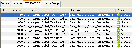
- From the bottom of the Data
Mapping tab, select
New.
A new Data Mapping window appears.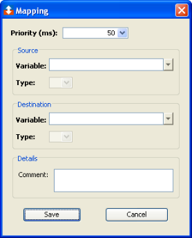
- Select a value for the Priority
(ms) parameter.
This is the frequency that the runtime Device Publisher feature will read the source device variable.
The units are in milliseconds (ms). - Select a Source Variable.
The list of devices are the Started devices on this node.
Expand the desired device and its internal structure until you can select the individual source device variable. - Select a Destination Variable.
The list of devices are the Started devices on this node.
Expand the desired device and its internal structure until you can select the individual destination device variable. - If the drivers support data transformation, the
data type fields will become active and can be changed
to a data type different than the variables' data
type.
- If the source device variable and the destination
device variables are arrays, enter the Count of
variables to transfer.
- Use the Save button to save the
definition of the data mapping.
The data mapping will appear in the list of data mappings for the node, in a Stopped state.
Viewing data mappings
The Data Mapping tab provides a list of data mappings defined on the node.
To use the Data Mapping tab, follow
these steps:
- From Workbench left pane, expand the node whose
data mapping you want to view.
- Select the Devices icon.
Then select the Data Mapping tab
Or, alternatively, select the Data Mapping sub icon. - The Data Mapping tab provides a
table format that lists the data mappings defined on
the node.
The top section of the Data mapping tab provides these columns:Column
Description
Priority
The priority of the data mapping, specified in the millisecond frequency that the runtime Device Publisher will read the source device variable.
Source
The source device variable.
Destination
The destination device variable.
State
The data mapping state, which can be:
Started - the data mapping is active. The runtime Device Publisher is reading the source device variable at the priority frequency.
Stopped - the data mapping is not active.
Disabled - indicating there is a problem communicating with the source device.Last Executed
Date and time when the data mapping was last executed, including the write to the destination device variable.
Successes
The number of successful data mappings from the source device variable to the destination device variable.
Failures
The number of failed data mapping. This is usually caused by the destination device not being in a Started state.
Overflow
The number of times the runtime Device Publisher cannot process the data mapping in a timely manner.
The entire node's definitions of data triggers, variable groups and data mappings defines the load on the runtime Device Publisher. Each of the Priority parameter values defines the list of device variables that need to read and processed that the Priority's millisecond frequency.
You might want to change the value set in the Priority parameter.
Data Mapping status information
The bottom portion of the Data Mapping
pane provide information concerning the performance of the
selected data mapping as follows:
| Parameter | Description |
|---|---|
| Source Device Name | The source device name. |
| Source Name | The source variable name. |
| Source Type | The data type of the source device
variable. |
| Source Count | When the source and destination
device variables are an arrays, the
number of source device variables from
the source array to transfer to the
destination device variable
array. |
| Source Length/Bit | For String data types, the length of
the source device variable. For BOOL
data types, the number of bits being
mapped. |
| Priority | The priority frequency in
milliseconds that the source device
variable is read by the runtime Device
Publisher. |
| Status | A pair of status values. The left
side value is the last result code for
the read of the source variable or the
write of the destination variable. This
is normally zero. The right side value is an internal data mapping status, which is different from the data mapping's State (Started, Stopped, or Disabled). |
| Successes | The number of successful data
mappings from the source device
variable to the destination device
variable. |
| Failures | The number of failed data mapping.
This is usually caused by the
destination device not being in a
Started
state. |
| Successes/Minute | The number of successful data
mappings per minute. This is an
approximation over the recent time
period. |
| Comment | The comment that was defined with
the data mapping. |
| Destination Device Name | The destination device
name. |
| Destination Name | The destination variable
name. |
| Destination Type | The data type of the destination
device variable. This can be different
from the source device variable
type |
| Destination Count | When the source and destination
device variables are an arrays, the
number of source device variables from
the source array to transfer to the
destination device variable
array. |
| Destination Length/Bit | For Bit data types, the number of destination device variable bits being mapped. |
| State | The data mapping state, which can
be: Started - the data mapping is active. The runtime Device Publisher is reading the source device variable at the priority frequency. Stopped - the data mapping is not active. Disabled - indicating there is a problem communicating with the source device. |
| Last State Change | The date and time of the last state
change of the data mapping |
| Last Fired | Date and time when the data mapping was last executed, including the write to the destination device variable. |
| Overflow | The number of times the runtime
Device Publisher cannot process the
data mapping in a timely manner. The entire node's definitions of data triggers, variable groups and data mappings defines the load on the runtime Device Publisher. Each of the Priority parameter values defines the list of device variables that need to read and processed that the Priority's millisecond frequency. You might want to change the value set in the Priority parameter. |
| User | The log in id of the user who
started the data mapping. This user's
security credentials are used to
determine the access rights to the
source and destination
variables. |
Controlling data mappings
When a data mapping row is selected in the table, the buttons at the bottom of the Data Mapping tab become enabled or disabled. This is based on the current state of the data mapping and the function of the button.
A single data mapping row or multiple data mapping rows
can be selected and then the function buttons used, but the
state of each data mapping will determine if the function
can be performed.
| Button | Description |
|---|---|
| New | Define a new data mapping. |
| Edit | Edit the data mapping definition. This can be used when the data mapping is in the Stopped state. This is only available for a single data mapping row selection. |
| Start | Available when the data mapping is in a Stopped state. Change the data mapping to the Started state. |
| Stop | Available when the data mapping is in the Started or Disabled state. Change the data mapping to the Stopped state. |
| Delete | Available when the data mapping is in the Stopped state. Delete the data mapping definition from the node. |
| Refresh | Refresh the information displayed in the Data Mapping tab. The Workbench will periodically refresh the information on its own without the Refresh button being used. |
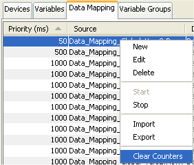
A data mapping row's pop-up menu can be displayed, and
the available options selected.