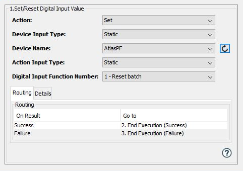
The Set/Reset Digital Input Value action is used to:
- Send a Set Digital Input command. This is performed
by sending a MID0224 command
to Set the digital input on the Atlas
Copco controller.
- The Set Digital Input Value allows the trigger to send digital input values that affect the configuration of a controller.
- Send a Reset Digital Input command.This is
performed by sending a MID0225 command
to Reset the digital input on the
Atlas Copco controller.
- The Reset Digital Input Value sends a digital input value to the controller and cancels the configuration change that was affected by the Set Digital Input Value.
Available digital input number values can either be selected when defining the action or can be dynamically retrieved from a value in a variable.
| Parameter | Description |
|---|---|
| Action | The options are:
|
| Device Input Type |
The method to supply the device name to the action. The options are:
|
| Device Name | Select an Atlas Copco device.
Displayed when
the Static option is selected in
the Device Input Type
parameter. |
| Action Input Type | The options are:
|
| Digital Input Function Number |
Displayed when the
Staticoption is
selected in the Action Input
Type parameter.
A list of the supported function
numbers that can be passed to the
controller. |
Input tab
| Parameter | Description |
|---|---|
| Device Name | Displayed when
the Dynamic option is
selected in the Device Input Type parameter.
The device name of the controller to send the Set or Reset Digital Input command. |
| Digital Input Function Number | Displayed when the
Dynamic option is
selected in the Action Input
Type parameter.
The function number to send to the Atlas Copco controller. Sending an invalid function number or a function number that isn't supported will result in an error for this trigger action. |
Digital Input Function Number
| Value | Description |
|---|---|
| 00 | Off |
| 01 | Reset Batch |
| 02 | Unlock Tool |
| 03 | Tool Disable n.o. |
| 04 | Tool Disable n.c. |
| 05 | Tool tightening disable |
| 06 | Tool loosening disable |
| 07 | Remote start pulse |
| 08 | Remote start continuous |
| 09 | Tool start loosening |
| 10 | Batch increment |
| 11 | Bypass PSET |
| 12 | Abort Job |
| 13 | Job off |
| 14 | Parameter Set toggle |
| 15 | Reset relays |
| 16 | Parameter Set select bit 0 |
| 17 | Parameter Set select bit 1 |
| 18 | Parameter Set select bit 2 |
| 19 | Parameter Set select bit 3 |
| 20 | Job select bit 0 |
| 21 | Job select bit 1 |
| 22 | Job select bit 2 |
| 23 | Job select bit 3 |
| 28 | Line control start |
| 29 | Line control alert 1 |
| 30 | Line control alert 2 |
| 31 | Ack error message |
| 32 | Fieldbus digIn 1 |
| 33 | Fieldbus digIn 2 |
| 34 | Fieldbus digIn 3 |
| 35 | Fieldbus digIn 4 |
| 36 | Flash tool green light |
| 45 | Parameter Set select bit 4 |
| 46 | Parameter Set select bit 5 |
| 47 | Parameter Set select bit 6 |
| 48 | Parameter Set select bit 7 |
| 49 | Job select bit 4 |
| 50 | Job select bit 5 |
| 51 | Job select bit 6 |
| 52 | Job select bit 7 |
| 53 | Batch Decrement |
| 54 | Job restart |
| 55 | End of cycle |
| 62 | Click wrench 1 |
| 63 | Click wrench 2 |
| 64 | Click wrench 3 |
| 65 | Click wrench 4 |
| 66 | ID card |
| 67 | Automatic mode |
| 68 | External monitored 1 |
| 69 | External monitored 2 |
| 70 | External monitored 3 |
| 71 | External monitored 4 |
| 72 | External monitored 5 |
| 73 | External monitored 6 |
| 74 | External monitored 7 |
| 75 | External monitored 8 |
| 76 | Select next parameter set |
| 77 | Select previous parameter set |
| 79 | Timer enable tool |
| 80 | Master unlock tool |
| 81 | ST scan request |
| 82 | Disconnect tool |
| 83 | Job select bit 8 |
| 84 | Parameter Set selected bit 8 |
| 85 | Request ST scan |
| 86 | Reset NOK counter |
| 87 | Bypass identifier |
| 88 | Reset latest identifier |
| 89 | Reset all identifier |
| 90 | Set home position |
| 91 | DigOut monitored 1 |
| 92 | DigOut monitored 2 |
| 93 | DigOut monitored 3 |
| 94 | DigOut monitored 4 |
| 95 | Disable ST Scanner |
| 96 | Disable fieldbus carried signals |
| 97 | Toggle CW/CCW |
| 98 | Toggle CW/CCW for next run |
| 99 | Set CCW |
| 105 | Logic digIn 1 |
| 106 | Logic digIn 2 |
| 107 | Logic digIn 4 |
| 108 | Logic digIn 4 |
| 109 | Logic digIn 5 |
| 110 | Logic digIn 6 |
| 111 | Logic digIn 7 |
| 112 | Logic digIn 8 |
| 113 | Logic digIn 9 |
| 114 | Logic digIn 10 |
| 120 | Forced CCW once |
| 121 | Forced CCW toggle |
| 122 | Forced CW once |
| 123 | Forced CW toggle |
| 129 | Parameter Set select bit 9 |
| 130 | Store current tightening program in the tool |
| 131 | Active XML result send |
| 132 | Tool in work space |
| 133 | Tool in product space |
| 134 | Flash tool yellow light |
| 135 | XML Emergency mode |
| 201 | Tool blue light IO controlled |
| 202 | Tool blue light |
| 203 | Tool green light IO controlled |
| 204 | Tool green light |
| 205 | Tool red light IO controlled |
| 206 | Tool red light |
| 207 | Tool yellow light IO controlled |
| 208 | Tool yellow light |
| 209 | Tool white light IO controlled |
| 210 | Tool white light |