Variables
The Siemens ERPC driver supports the following Siemens
S7-300 PLC registers as device variables:
|
Variable |
Description |
|---|---|
| I | Standard input registers that are tied to physical inputs on a Siemens S7 Module. This area of memory can only be read by the Siemens ERPC driver and cannot be written. Each Input point is BIT based and can be accessed as a BOOL. |
| Q | Standard output registers that are tied to physical outputs on a Siemens SM Module. This area of memory can be read or written to by the Siemens ERPC driver. Each output point is BIT based and can be accessed as a BOOL. |
| M | This area of memory can be read or written to by the Siemens ERPC driver. Each input/output point is of type UINT1 and can be accessed as a BOOL. |
| DB | Data blocks. This data region can be defined as contiguous regions (DB1,DB2,DB2…) or non-contiguous (DB1, DB5, DB100…). Data blocks are contiguous blocks of memory where variables can be defined and accessed as any of the supported data types. |
| Symbols | Named variables within a Siemens S7-300 PLC. |
Data types and data conversion
The Siemens ERPC driver supports the Siemens S7-300 PLC
data types and their mapping to runtime data types as
follows:
|
Siemens data type |
Runtime data type |
|---|---|
| Byte | UINT1 |
| Char | INT1 |
| Word | UINT2 |
| INT | INT2 |
| DWord | UINT4 |
| DINT | INT4 |
| Real | FLOAT4 |
| Bool | BOOL |
| String | STRING |
| DATE_AND_TIME | TIMESTAMP |
The Siemens PLC data types are supported in the runtime
environment wherever a variable is accessed and the
variable is associated with a Siemens S7-300 PLC device.
Some examples are:
- Workbench Variables window Read as and Write as functions
- Transport map data type parameters
- Trigger data type parameters
- Trigger action variable data type parameters.
The data representations in the Siemens S7-300 PLC, the runtime and the Workbench are supported by the necessary data conversion functions.
Addressing
Absolute and Symbolic addressing are supported by the Siemens ERPC driver and deviceWISE. Each of these addressing methods are described in the sections that follow. It is important that the user understand the configuration of the PLC register area as defined using the Step 7 software and how this relates to the access from within deviceWISE.
Absolute Addressing
For absolute addressing, the Siemens ERPC driver and deviceWISE enumerates the register area and data blocks as byte arrays. Each byte array is represented as follows:
<Register or DB Number> [byte array offset]
For example, DB2[0] represents the data block DB2 offset 0.
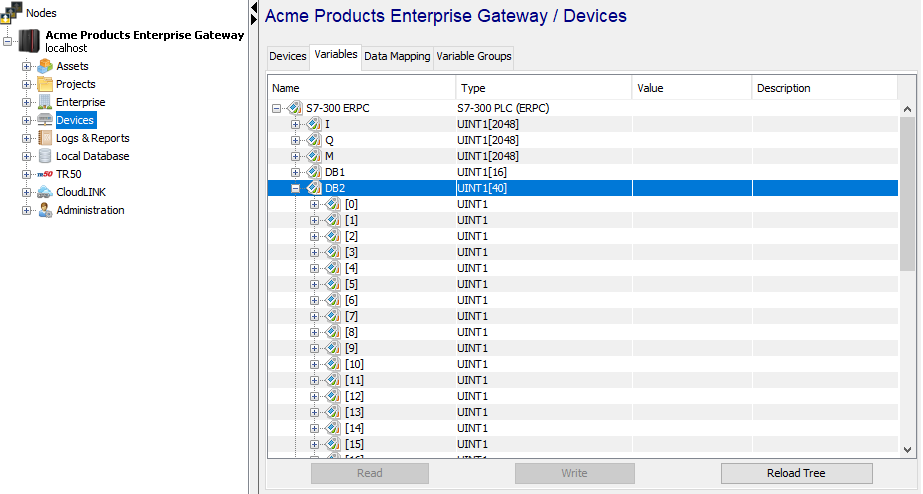
The DB arrays are visible through the Variables window in the Workbench as byte arrays. The actual arrangement of device blocks in memory may be different from byte arrays. This arrangement is not visible to deviceWISE. Regardless of how the data blocks are arranged in the PLC memory the Siemens ERPC driver will always enumerate them as byte arrays.
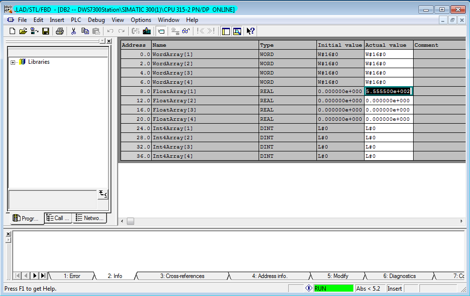
The following example shows 3 separate regions of a data block DB2 in PLC memory as viewed through the STEP 7 software: a word array, a float array and a dint (dword) array.

The same data block as seen through the Variables window of the Workbench.
The following table compares the addressing scheme of
the DB2 block as viewed in the STEP 7 software to the view
in the Variables window in
deviceWISE.
| Address Range (STEP 7) | Data Type | Length | Array Range (deviceWISE) |
|---|---|---|---|
| 0.0 – 6.0 | WORD | 8 bytes | DB2[0] – DB2[7] |
| 8.0 – 20.0 | FLOAT4 | 16 bytes | DB2[8] – DB2[23] |
| 24.0 – 36.0 | DWORD | 16 bytes | DB2[24] – DB2[39] |
Data block addressing using the Workbench Variables window
The following example demonstrates how to write a value to the FLOAT array defined in the Siemens PLC staring at address 8.0 using the Workbench.
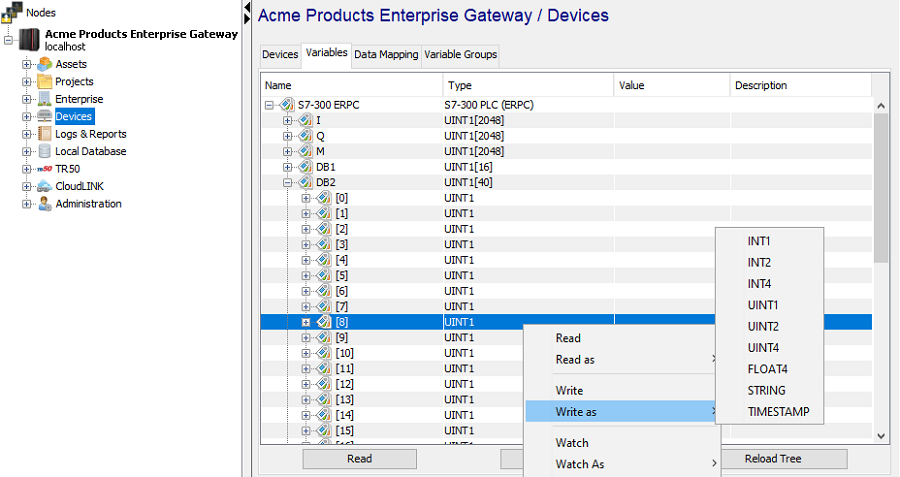
Since the float array begins from array offset DB2[8], follow these steps to write a value to that address in the PLC.
- Right click on DB2[8] in the
Variables window of the Workbench.
This should display a context menu that lists all the
supported actions that can be performed on variable
DB2[8].
- Select the “Write as” option. A sub-menu displaying
all the supported types DB2[8] can be written as, is
displayed.
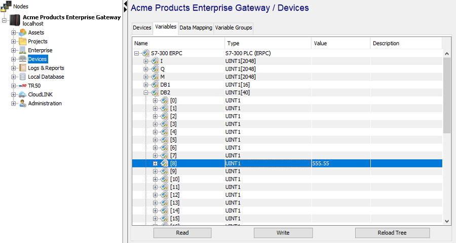
- Click on FLOAT4 (or REAL, depending on your
platform) and in the value text box enter 555.55 and
click OK.
- You should see the float value 555.55 displayed in
the Workbench Variables window at
DB2[8].
- Verify the value is written to the
correct PLC address through the STEP 7
software.
Data block addressing when defining a Trigger
The example below shows how the same variable in the PLC is accessed from a Trigger, using it as the source of a Set action. Note the variable naming scheme of device_name.variable where the variable is the data block address DB2[offset 8].
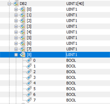
Data block bit addressing
deviceWISE allows for the addressing of individual bits of a DB byte. For example, DB2[8] bit 0 is accessed as DB2[8]/0 and bit 7 is accessed as DB2[8]/7.
When viewed using the Workbench’s Variables panel, the individual bits are display and accessed as shown in this example:
When referenced in a trigger action,
the individual bits can be accessed as shown in this
example Set action:
Symbolic addressing
For Symbolic addressing, the Siemens ERPC driver and deviceWISE access the Symbols that have been defined for the S7-300 PLC using the STEP 7 or TIA Portal software.
Symbolic addressing has the advantage of using understandable symbol names for the data items without having to coordinate the absolute address and date types of the data items.
Symbolic addressing with STEP 7 software
There are specific Step 7 software configuration tasks that are required to define and expose the symbols.
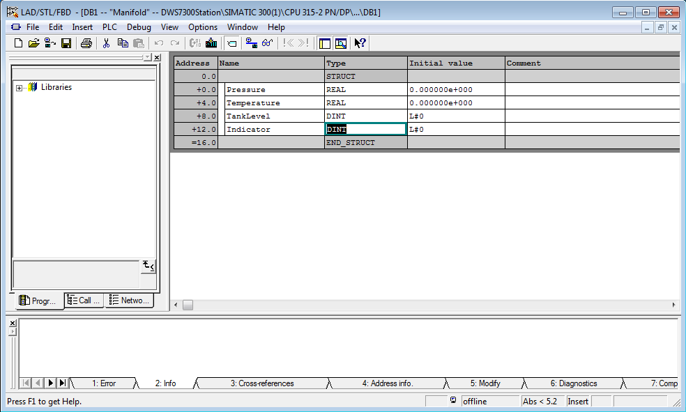
Step 1
Define data items within a data block using the normal procedure which can be manually entering into the data block or generating them using a source file.
Note: UDT variables are not supported.
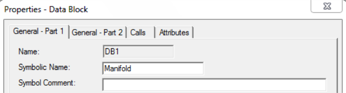
Step 2
Assign a symbolic name to the data block. Open the Properties of the data block and set the “Symbolic Name” field. Within deviceWISE all variables will be named devicename.Symbolic Name.tagname
In the example below, the data block is named “Manifold”
Step 3
Once all the variables have been defined within a data
block and the data block has been assigned a Symbolic Name
we can proceed to the Hardware Config panel and select the
ERPC module, then select the “ERPC Symbols” tab:
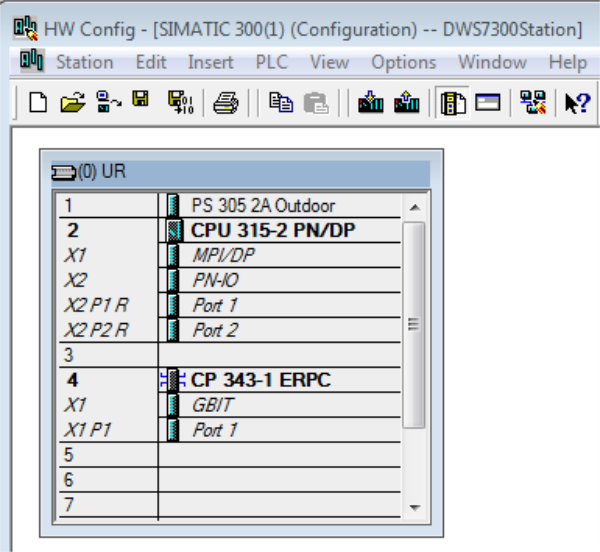
- Select the CP 343-1 ERPC
- When the Properties panel is displayed select the tab ERPC Symbols
- On the left panel select the Symbolic Name you gave the data block, in this case “Manifold”
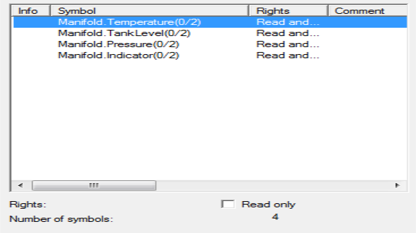
- When selected all tags are then displayed on the
right pane, as shown in the example below:

At this point you can select one or all symbols and select “Apply”.
Also, if some of these tags need to be written (write access as well as read access) then deselect the “Read only” check.
Step 4
Once the above panel is closed the final step is to compile and download the configuration to the PLC CPU.
Note: this compilation and download
affects only the hardware configuration which includes
information about the symbols, such as what physical data
block they reside in, size and type.
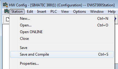
To compile the configuration use the Station menu and
select Save and Compile:
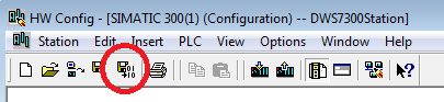
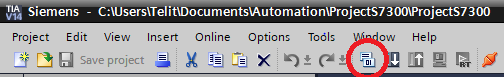
Or select the action bar compile icon:
In order for the system to work the actual data block that contains the selected symbols has to be present in the PLC CPU when the hardware configuration is downloaded. If the entire station is downloaded then both the hardware configuration and data blocks will be downloaded at the same time. It is important to keep both configurations in sync. If items are added or deleted to the data block it is recommended that the Hardware config process is performed again.
Final step
For the changes to take effect in deviceWISE after a download, Stop and Start the Local CPU 1 / S7-300 PLC (ERPC) device. The information deviceWISE processed after the download and on reboot is consumed only during the Start of the Local CPU 1 device.
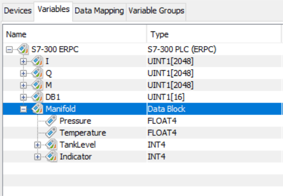
After the Stop and Start of the Local CPU1 device, the variables panel can be used to display the variables for the device. The “Manifold” label corresponds to the data block symbol name.

Symbolic addressing with TIA Portal software
There are specific TIA Portal software configuration tasks that are required to define and expose the symbols.
Step 1
Define data items within a data block using the normal procedure which can be manually entering into the data block or generating them using a source file.
Note: UDT variables are not supported.
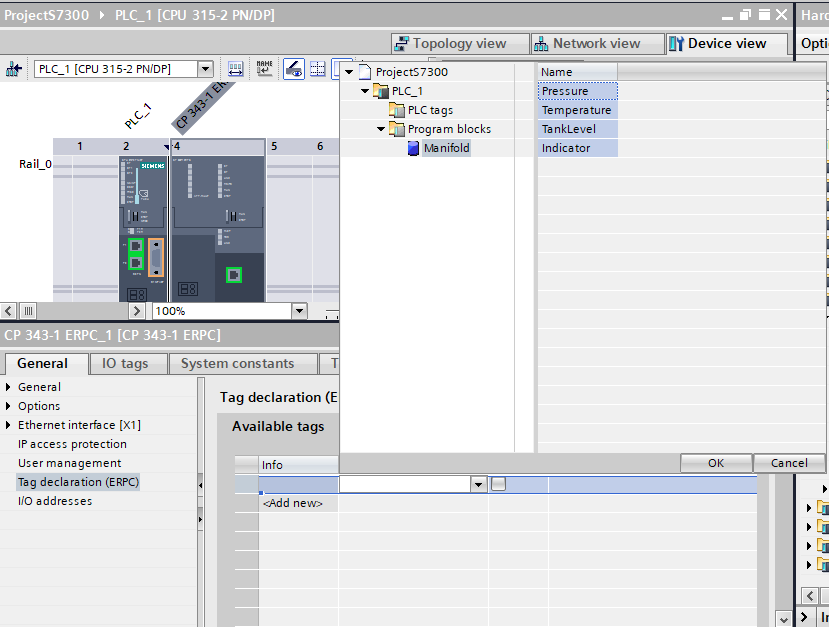
In the example below, the data block is named “Manifold”:

Step 2
Once all the variables have been defined within a data block, open the "Device configuration" panel and select the ERPC device on the rail. In the "Properties" panel below, select the "Tag Declaration (ERPC)" option in the "General" tab.
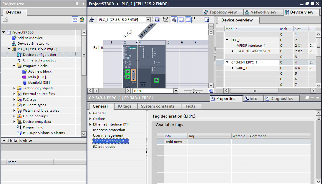
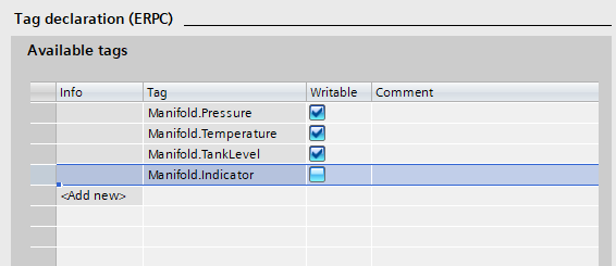
Click on the "<Add new>" prompt in the "Available tags" table. Then choose one or more tags to be added from the drop down menu in the "Tag" column.
If some of these tags need to be written (write access as well as read access), then check the box in the tag's "Writable" column.
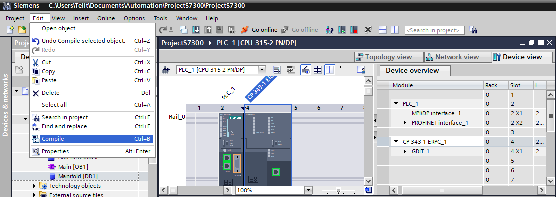
Step 3
Now the configuration needs to be compiled and downloaded to the PLC CPU.
Note: This compilation and download
affects only the hardware configuration which includes
information about the symbols, such as what physical data
block they reside in, size and type.
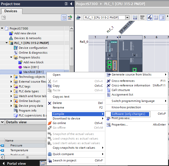
To compile the configuration, select the ERPC device on the
rail in the "Device configuration" panel and click
"Compile" from the Edit menu:
Or select the action bar compile icon:
If an error is shown in the "Compile" tab of the "Info" panel, try compiling the altered data block(s) individually. Then try to compile the hardware configuration again.
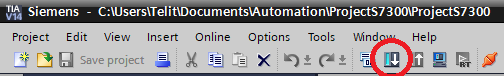
Download the changes to the PLC by selecting the "Download to device" icon in the action bar:
In order for the system to work the actual data block that contains the selected symbols has to be present in the PLC CPU when the hardware configuration is downloaded. If the entire station is downloaded then both the hardware configuration and data blocks will be downloaded at the same time. It is important to keep both configurations in sync. If items are added or deleted to the data block it is recommended that the Hardware config process is performed again.
Final Step
For the changes to take effect in deviceWISE after a download, Stop and Start the Local CPU 1 / S7-300 PLC (ERPC) device. After the Stop and Start of the device, the variables panel can be used to display the variables for the device. The "Manifold" label corresponds to the data block symbol name.
Symbolic addressing using the Workbench Variables window
The example below shows a variable in the PLC being accessed using its Symbol definition name of Manifold.Temperature. The actual data block address is not needed and the data type is provided.
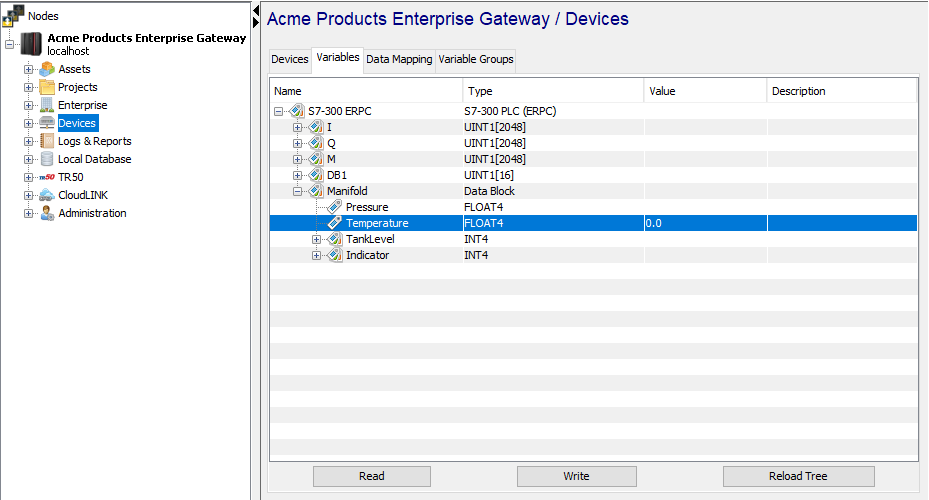
The Symbols only field in the S7-300 PLC (ERPC) device definition allows you to limit the display of Variables to symbols only for a device. Specify True to only display symbols in the Variables window or False to display symbols and data blocks. Limiting the display to symbols only can be one way to limit access to data blocks.
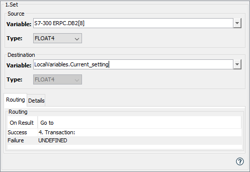
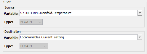
Symbolic addressing when defining a Trigger
The example below shows how the same variable in the PLC is accessed from a Trigger, using it as the source of a Set action. Note the variable naming scheme of device_name.variable where the variable is the Symbol Manifold.Temperature.
String data type
When accessing a Siemens PLC’s data blocks as a string data type, you need to be familiar with how strings are represented in the data blocks. The data type string represents a character string of up to 254 characters. A variable with the data type string occupies two additional bytes in memory to hold the maximum string length and the actual string length. The first byte holds the maximum string length (maximum number of characters), which can be up to 254. The second byte holds the actual string length. The character string then begins starting at the third byte.
For example, a string with a maximum length of 10 characters and a current character string of “hello” will be accessed in the PLC at data block DB500, starting at offset 0. This variable’s address is represented in the Variables window as DB500[0].
- The string’s maximum length of 10 occupies DB500[0]
- The string’s actual length of 5 occupies DB500[1]
- The string’s characters, starting with “h” occupies DB500[2], “e” at DB500[3], “l” at DB500[4], “l at DB500[5] and “o” at DB500[6].
When accessing a string data type using the Symbol addressing support, you do not need to worry about the first two control bytes. The Siemens ERPC driver handles the control bytes.
Siemens Logic Trigger
The Siemens ERPC driver and deviceWISE support an ERPC specific event referred to as a logic trigger. This event occurs when the S7-300 PLC executes a FB56 instruction. This feature allows the program on the PLC to notify a trigger in deviceWISE that some condition has been met and should be acted upon. This form of an unsolicited event allows the deviceWISE trigger to be notified without having to constantly poll the PLC to identify when an event occurs. Using this approach keeps backplane communications to a minimum (no polling or scanning a variable for a data change). The logic trigger feature includes the ability to configure specific variables, so that the deviceWISE trigger actions have access to those variable values without having to re-access the PLC.
Siemens FB56 instruction
Refer to the Siemens documentation for details on programming the FB56 instruction:
- SIMATIC NET Functions (FC) and function blocks (FB) for SIMATIC NET S7 CPs, Siemens, C79000-G8976-C229-03
- Interfacing a CP 343-1 ERPC with MES/ERP via Database Systems, Siemens, Entry ID: 42321509
The S7-300 PLC has support for up to 16 instances of the FB56 instruction. Each instance can be mapped to a unique deviceWISE trigger.
When the FB56 instruction is executed a data transmission to deviceWISE takes place, including the configured PLC variables. The FB56 instruction has the option to wait for completion of the deviceWISE trigger before continuing.
deviceWISE trigger
A deviceWISE trigger to execute when the FB56 instruction is executed is defined to be of Trigger Event Type = PLC Logic Events.Siemens FB56.
The definition phase for the trigger is where you specific the configuration values that tie this deviceWISE trigger to the specific FB56 instruction. You also configure the specific PLC variable values that are sent to deviceWISE and are directly available to the trigger as event variables. This removes the need for the trigger to access the PLC to read the variable values.
When the deviceWISE trigger executes, the configured PLC variable values can be used to complete the specific application logic that is required (for example: insert data into a database). The deviceWISE trigger indicates its completion status (success, failure, etc.) back to the FB56 instruction by setting a result status variable. This allows the deviceWISE trigger logic and the S7-300 PLC logic to coordinate actions in both environments.
Example FB56 instruction and deviceWISE trigger flow
This section contains an example of defining the FB56 instruction in the S7-300 PLC and the corresponding deviceWISE trigger to show how the two environments work together.
Example FB56 instruction
On the S7-300 side, a FB56 is used with parameters that will be referenced in the deviceWISE trigger. Refer to the Siemens documentation for details of the FB56 instruction. An example of a FB56 is shown here:

Creating the deviceWISE trigger
The concepts and example steps associated with the deviceWISE trigger are show below:
- From the bottom of the Triggers window, click
New
- From the Trigger Event Type drop
down-list, expand PLC Logic Events,
and then click Siemens FB56.
The Trigger window changes to accommodate the selected Trigger Event Type.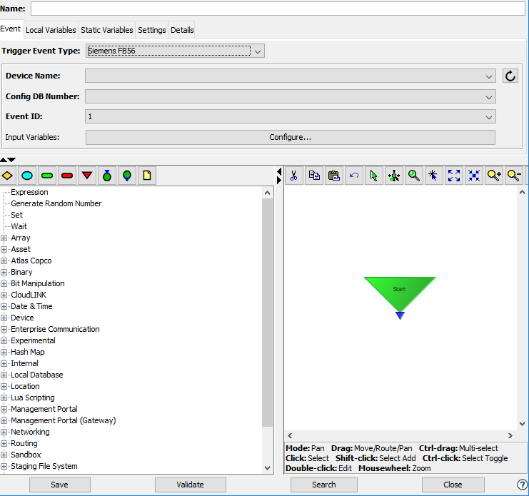
-
Set the trigger's fields as follows:
Field Description Name Enter a name for the trigger. Reporting Choose a reporting option. Max Pending Enter 1 to indicate that the first instance of the trigger must complete execution before another instance is created. Max Exec Time (ms) Enter the maximum execution time of the trigger, which if exceeded will result in a warning message written to the Exceptions Log file. Trigger Event Type Expand PLC Logic Events and select Siemens FB56. Device Name Select one of the available devices. The Local CPU1 represents the S7-300 in the same SIMATIC station as the CP 343-1. Devices must be in the Started state to appear in this list. Config DB Number The drop-down provides a list of message configuration data blocks in the S7-300 PLC. Select the number that matches the value specified in the CONF_DB parameter of the FB56 instruction. Event ID The drop-down provides a list of identifiers for the logic trigger. Select the number that matches the value specified in the ID parameter of the FB56 instruction. The Event ID and Config DB Number fields tie the deviceWISE trigger to the FB56 instruction in the S7-300 PLC. Input Variables Click the configure button to define the PLC variables that will be sent to this deviceWISE trigger. This is explained in the next step. - Adding Input Variables. Click the Configure button
to define the PLC variables that will be sent to this
deviceWISE trigger.
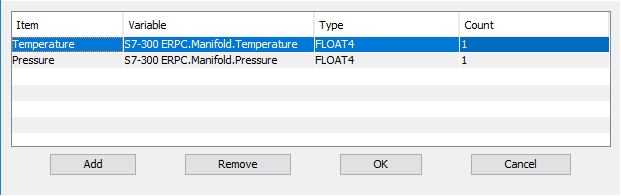
An Items window is displayed
- Use the Add button to add PLC
variables. Click in each Item’s Variable field and use
the drop-down to display the list of the device’s
variables. These PLC variables can be referenced by
absolute address or by symbolic address.
- As you add input
variables, each item is given a default name as Item 1,
Item 2, Item 3, etc. You can click on each item name
and give it a more meaningful name as shown for the
example Temperature item below.
- Continue to add or remove input variables until you have
the list of PLC variables to be sent to the deviceWISE
trigger when it executes.
Complete the definition of the trigger and click the Validate button to verify all fields. Click the Save button to save the definition of the trigger. - Communicating the required PLC variables to the S7-300
PLC.
When the deviceWISE trigger is Started, this configuration information is sent to the PLC and stored in the Config DB. - FB56 Instruction
execution.
When the FB56 instruction is executed in the S7-300 PLC, these PLC variables are sent to the deviceWISE trigger and made available as Event Variables for use in the trigger actions. An example is seen below as the source of a Set action.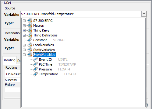
- Communicating the status of the
deviceWISE trigger back to the FB56 instruction. The
deviceWISE trigger has the responsibility of
communicating its completion status back to the FB56
instruction.This is accomplished
by using the trigger Event
Variable EventVariables.ResultStatus. An
example is seen below where the routing of the
Transaction action will dictate the setting of a
result value or 1, 2 or 4.

The values defined for the communicating the deviceWISE trigger completion status back to the FB56 instruction using the ResultStatus are:- 1 = OK
- 2 = A Transaction action received a Store and Forward result
- 4 = Error
deviceWISE Trigger Considerations
It is important to realize that the execution of the actions in the deviceWISE trigger must complete before the ResultStatus is communicated back to the FB56. Keeping the actions to a minimum will keep this execution time to a minimum.
Be careful about using trigger reporting options because trigger reporting requires additional processing resources. If the Transaction action is required in the trigger be careful about using transport mapping log options.
Limitations
- For a TIMESTAMP data type, the daylight savings time and time zone information for the deviceWISE node is maintained for the current calendar year only. Accessing a TIMESTAMP outside of the current calendar year will use the information for the current year and may not return the expected value (e.g. a prior year that has a different daylight savings time start date).
- For a STRING data type the maximum supported length
is 254 bytes.