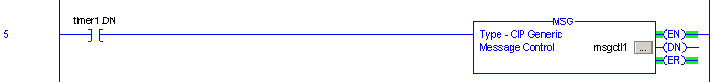
The following section describes defining a Rockwell Software RSLogix 5000 by adding a rung of a ladder and configure a message instruction that will trigger an event in the Rockwell driver. To add a message structure to the global tag space, do the following:
- Create a rung of a ladder
to send the message instruction. For more information on creating a ladder, see Logix 5000 Controllers Messages
- On the Configuration tab, click on the button next to the message name
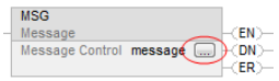
A dialog box appears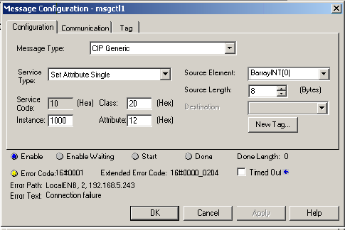
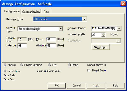
The Rockwell driver supports two message types: CIP Generic or CIP Data Table Write. The driver also supports the Write Tag Fragmented message type, which the Logix PLC will send if the size of the data payload for a CIP Data Write message exceeds approximately 500 bytes. The configuration panel shown above is for a CIP Generic message type. The Rockwell driver supports three CIP Generic Service Types: Set Attribute Single, Get Attribute Single, and Custom. The panel above shows the fields associated with the definition of the Set Attribute Single Service Type. The next section will provide detail on the values that should be entered into this panel for each Message Type / Service Type that the Rockwell driver supports. - Click on the Communication tab
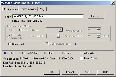
Do the following: - The Path should be set to the proper path to reach
the node that contains the trigger to execute. In
general, the path will be first to the Ethernet module
in the rack, then 2 (for Ethernet), and the IP address
of the node.For example:
LocalENB, 2, 192.168.5.243
where:- LocalENB is the name assigned to the Ethernet module in the PLC rack.
- 2 indicates that the next path is an Ethernet route.
- 192.168.5.243 is the IP
address of the node.
Refer to your RSLogix 5000 documentation for more information.The message will be routed to port 44818, which is the default CIP port. If the Rockwell Logix Unsolicited Listener is listening on a port other than 44818, the port must be specified in the Path field. To specify the port, append the colon character ( : ) followed by the port number, to the path. For example: LocalENB, 2, 192.168.5.243:49313 where 49313 is the port the Rockwell Logix Unsolicited Listener has opened to receive messages.When using the L84 CPU, the message will be sent using the built-in Ethernet port, the communication path is shortened because the Ethernet module is not referenced. For Example: 2, 192.168.5.243. A port is specified in situations where the Rockwell Logix Listener is receiving messages on a port other than 44818. For Example 2, 192.168.5.243:49313
- The Connected check box is optional. If selected, a CIP connection will be opened before sending the message.
- Large Connection - The standard CIP connection allows messages with up to 500 bytes of data. A CIP Large Connection may be used to allow up to 3980 bytes of data. To use Large messages with a ControlLogix controller, the following are required:
- 1756-EN2T(R) or 1756-EN3TR modules at revision 5.x and higher for sockets support.
- Logix Designer application, version 21.00.00 or later, or RSLogix 5000 software, version 20.00.00 or later.
- The Large Connection and Connected check boxes must be checked, as shown below:
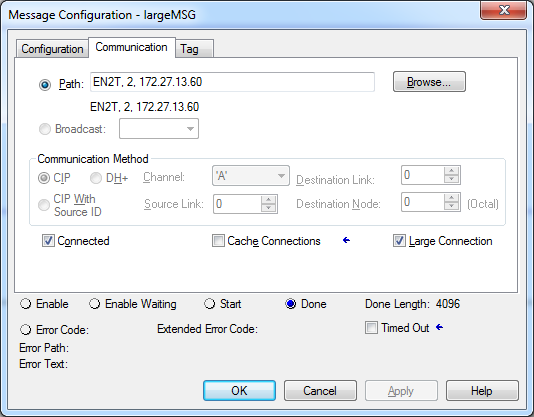
The RSLogix Message Configuration panel shown above
illustrates the definition of a Set Single Attribute
message. This message type is an example of an unsolicited
message that will send data to a trigger.
- Instance, Class, Attribute: Can be any combination, the event will use these three values to establish a match to find the correct trigger to execute.
- Source Element: Can be any tag in the PLC whose data will be sent to the trigger.
- Source Length: The number of data bytes to send, this number must not exceed the size of the tag defined in the Source Element field
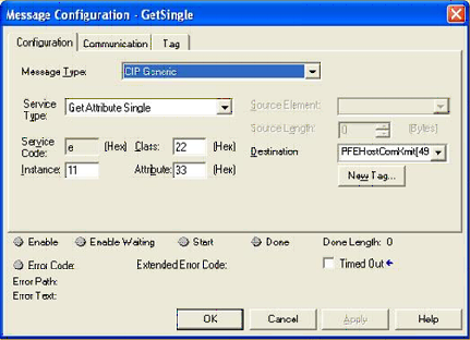
The panel above shows the fields associated with the
definition of the Get Attribute Single Service Type. This
Service Type is an example of an unsolicited message that
will receive data from a trigger.
- Instance, Class, Attribute: Can be any combination, the event will use these three values to establish a match to find the correct trigger to execute.
- The Destination is where the MSG instruction will put the data retrieved from the node. Notice that there is no “Destination Length” in the MSG instruction. The Rockwell driver will specify how many bytes to send but the Destination location must have enough room to contain the data upon receipt.
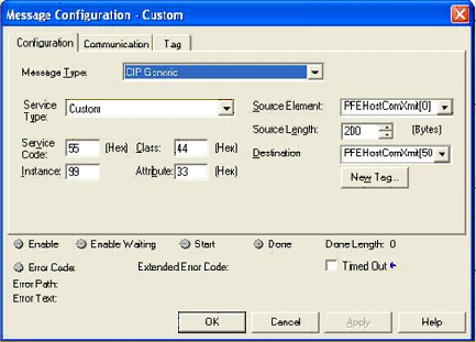
The panel above shows the fields associated with the
definition of the Custom Service Type. This Service Type is
a hybrid of both the Set Attribute Single and Get Attribute
Single Service Types. This unsolicited message sends data
to a trigger but also receives data from the same
trigger.
- Service Code, Instance, Class, Attribute: Can be any combination, the event will use these four values to establish a match to find the correct trigger to execute.
- Source Element: Can be any tag in the PLC whose data will be sent to the trigger.
- Source Length: The number of data bytes to send, this number must not exceed the size of the tag defined in the Source Element field
- The Destination is where the MSG instruction will put the data retrieved from the node. Notice that there is no “Destination Length” in the MSG instruction. The Rockwell driver will specify how many bytes to send but the Destination location must have enough room to contain the data upon receipt.
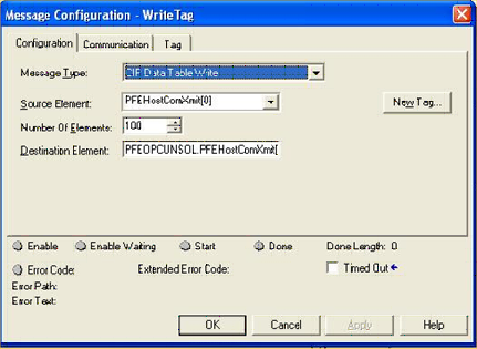
If using the Data Table Write feature, check if the Cached option is selected. It is advised to deselect it, seeing that messages bigger than 480 bytes are prone of being fragmented. The cached option could lead to the continued resending of the last fragmented message by the PLC, which will confuse the Listener.
This panel illustrates the definition of the CIP Data Table
Write message. The Data Table Write message is typically
used to write an element group defined on one Logix PLC to
another Logix PLC. A node can be defined as the destination
of this message, rather than a second Logix PLC.
- Source Element: Can be any tag in the PLC whose data will be sent to the trigger.
- Number of Elements: The number of data elements within the tag defined in the Source Element field that will be sent to the trigger.
- Destination Element: Traditionally this is the name of a tag on a second Logix PLC where the data will be written. For the Rockwell driver support of this type, this name is used to identify a trigger that will execute upon receipt of the unsolicited message.
The Write Tag Fragmented Service allows the PLC to send
data that will not fit into a single packet (approximately
500 bytes), to the Rockwell driver's Unsolicited Listener.
It does so by issuing a series of requests to the Listener,
passing along all of the data for a large tag object using
this service.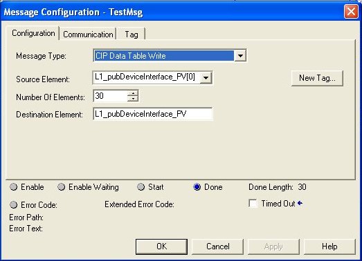
This panel shows the definition of a CIP Data Table
Write message. The difference between this panel and the
one shown in the previous example is the tag selected in
the Source Element field. In this example the data type for
this tag is User Defined Tag (UDT). At execution time this
message will be send the data for thirty UDT elements to
its destination.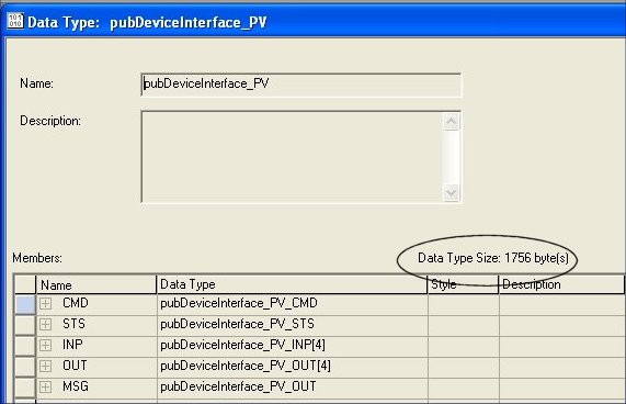
This panel shows the size of the UDT that the tag is associated with. The message will be sending 52,680 (1756 * 30) bytes of data when the ladder executes this function. The PLC will determine that the data for this message exceeds what can fit into a single packet and will send a Write Tag Fragmented message, rather than a Data Table Write message.