-
The following section shows an example of the Rockwell Software RSLogix 5 connected to a PLC-5 and the steps necessary to add a rung of a ladder and configure a message instruction that can send an event notification to the Rockwell driver.
Add a MESSAGE (MSG) structure to the global tag space. It can be named anything you want. - Add a
rung of a ladder to send the message instruction.
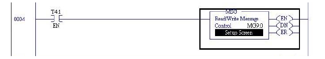
- Configure the message
instruction by clicking the “Setup Screen” button. You will
see a dialog box similar to the following.
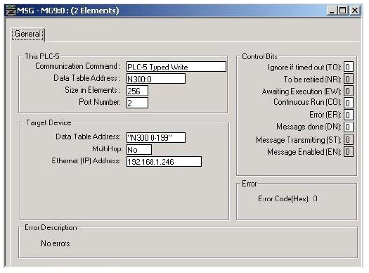
- Here are some notes on the important parameters of the above configuration panel:
- Communication Command: Must be either PLC-5 Typed Write or PLC-2 Unprotected Write.
- Data Table Address (This PLC-5): Identifies the beginning tag that will be sent to the node in the unsolicited message.
- Size in Elements: The number of elements to send, not the size of the elements. In the example above, 256 Integers, 512 bytes in all, will be packaged in the unsolicited message.
- Data Table Address
(Target Device): For PLC-5 Typed Write messages: This may
be either a Symbolic or Logical address:
- Symbolic - A string that uniquely identifies each unsolicited message. Notice in the example above how the string is enclosed within quotation marks. This identifies the use of Symbolic Data Table addressing. It can be any text to be used to match a Workbench trigger definition.
- Logical Binary - This must be a valid logical address on the PLC-5 and must NOT be enclosed in quotation marks. For example: N300:0
- For PLC-2 Unprotected Write messages: A unique number in octal format must be supplied that uniquely identifies the unsolicited message. The number must be in the octal range of 0 to 37777.
- The Rockwell driver will use the Data Table Address value to establish a match to find the correct trigger to execute. The Data Table Address value entered here will be entered on the trigger definition panel so that this message is associated with a specific trigger.
- Ethernet (IP) Address: The IP address of the node that will receive the unsolicited message.
The use of the Rockwell unsolicited message requires that the rate of the logic events causing triggers to execute be synchronized with the rate of the trigger’s execution. In other words, the unsolicited messages should be paced to allow the trigger to finish its execution before another unsolicited message is sent.
DF1 Encapsulated CIP Messages
PLC-5 Typed Write and PLC-2 Unprotected Write messages can also be sent over a CIP link using a Data Highway card. These messages use the DF1 format encapsulated inside a CIP message. The Rockwell driver Unsolicited Logix Listener device receives these messages. A trigger can be defined with an event type of Rockwell (CIP) to execute when a message is sent from the PLC.
The following shows an example of the message instruction configuration for sending PLC-5 Typed Write messages encapsulated in CIP message:
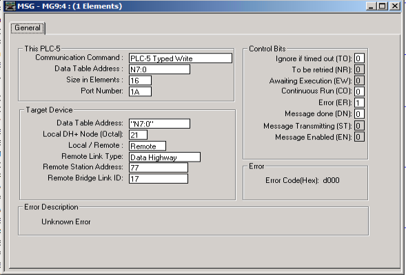
Note that the Remote Station Address is an octal value, even though it is not marked as such (eg, 077 = 63).
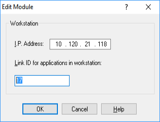
The Remote Bridge Link ID (eg, 17) must be set to the same value that is defined for the Workstation Link ID, using the RSLinx software (see below).
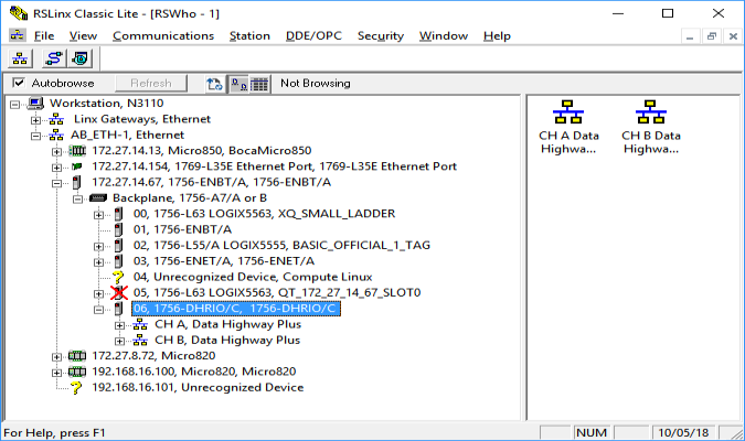
Using RSLinx to configure the Workstation Link ID
- Open RSLinx and browse to the
DHRIO slot:
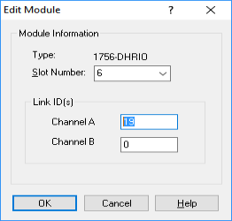
- Right-click on the DHRIO slot and select Module Configuration.
- Select the Routing Table
tab:
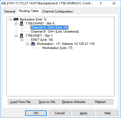
- Right-click on either Link to
change its Link ID. The destination IP address is also
set along with the Workstation Link ID: