The following section shows an example of the Rockwell Software RSLogix 500 connected to a SLC 500 and the steps necessary to add a rung of a ladder and configure a message instruction that can send an event notification to the Rockwell driver.
- Add a MESSAGE (MSG) structure to the global tag space. It can be named anything you want.
- Add a rung of a ladder to send the message
instruction.
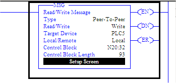
- Configure the message instruction by clicking the
“Setup Screen” button. You will see a dialog box
similar to the following.
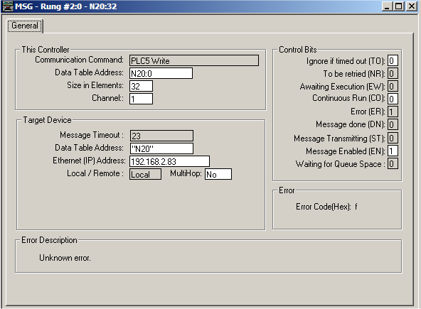
- Here are some notes on the important parameters of
the above configuration panel:
- Communication Command: Must be PLC5Write.
- Data Table Address (This Controller): Identifies the beginning tag that will be sent to the node in the unsolicited message.
- Size in Elements: The number of elements to send, not the size of the elements. In the example above, 32 Integers, 64 bytes in all, will be packaged in the unsolicited message.
- Data Table Address (Target Device): A string that uniquely identifies each unsolicited message. Notice how the string is enclosed within quotation marks, this identifies the use of Symbolic Data Table addressing. Currently only Symbolic Data Table addressing is supported by the Rockwell driver when sending a PLC5Write message.
- Ethernet (IP) Address: The IP address of the node that will receive the unsolicited message.
The use of the Rockwell unsolicited message requires that the rate of the logic events causing triggers to execute be synchronized with the rate of the trigger’s execution. In other words, the unsolicited messages should be paced to allow the trigger to finish its execution before another unsolicited message is sent.