Variables
The Siemens S7 driver supports the following Siemens PLC
registers as device variables:
| Variable | Description |
|---|---|
| I | Standard input registers that are tied to physical inputs on a Siemens S7 Module. This area of memory can only be read by the Siemens S7 driver and cannot be written. Each Input point is BIT based and can be accessed as a BOOL, UINT1, UINT2 or UINT4. |
| Q | Standard output registers that are tied to physical outputs on a Siemens S7 Module. This area of memory can be read or written to by the Siemens S7 driver. Each output point is BIT based and can be accessed as a BOOL, INT1, INT2, INT4, UINT1, UINT2, UINT4, FLOAT4 or STRING. |
| M | Standard bit registers on a Siemens S7 Module. This area of memory can be read or written to by the Siemens S7 driver. Each input/output point is BIT based and can be accessed as a BOOL, UINT1, UINT2 or UINT4. |
| DB | Byte-based device blocks. This data region can be defined as contiguous regions (DB1,DB2,DB3…) or non-contiguous (DB1, DB5, DB100…). It can be accessed as BOOL, INT1, INT2, INT4, UINT1, UINT2, UINT4, FLOAT4, STRING or TIMESTAMP. |
Data types and data conversion
The Siemens S7 driver supports the Siemens PLC data
types and their mapping to runtime data types as
follows:
| Siemens data type | Runtime data type |
|---|---|
| Bit | BOOL |
| UINT1 | INT1 |
| UINT1 | INT2 |
| UINT1 | INT4 |
| UINT1 | INT8 |
| UINT1 | UINT1 |
| UINT1 | UINT2 |
| UINT1 | UINT4 |
| UINT1 | UINT8 |
| UINT1 | FLOAT4 |
| UINT1 | STRING |
| UINT1 | TIMESTAMP |
The Siemens PLC data types are supported in the runtime environment wherever a variable is accessed and the variable is associated with a Siemens PLC device. Some examples are:
- Workbench Variables window Read as and Write as functions
- Transport map data type parameters
- Trigger data type parameters
- Trigger action variable data type parameters.
The data representations in the Siemens PLC, the runtime
and the Workbench are supported by the necessary data
conversion functions.
Addressing
The Siemens S7 driver enumerates the data blocks as byte arrays. Each byte array is represented as follows:
<DB block Number> [byte array offset]
e.g. DB3[0] represents the data block DB3 Address 0.
The DB arrays are visible through the Variables window in the Workbench as seen below. The actual arrangement of device blocks in memory may be different from byte arrays. This arrangement is not visible to the Siemens S7 driver. Regardless of how the data blocks are arranged in the PLC memory the Siemens S7 driver will always enumerate them as byte arrays.
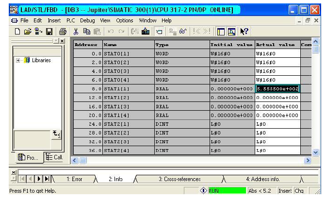
The following example shows 3 separate regions of a data
block DB3 in plc memory as viewed through the STEP 7
software: a word array, a float array and a dint (dword)
array.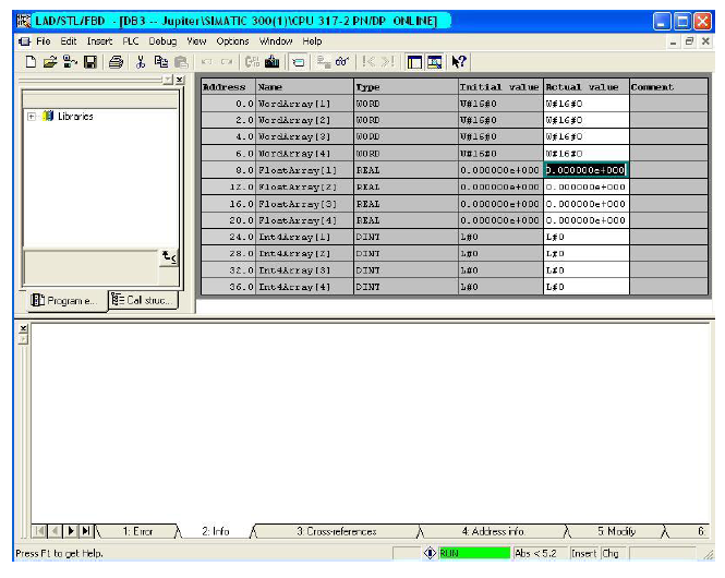
The same data block as seen through the
Variables window of the Workbench.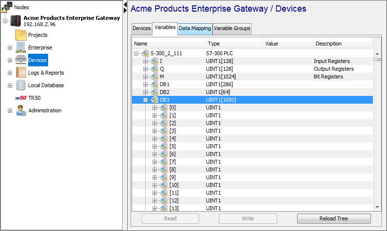
The following table compares the addressing scheme of the
DB3 block as viewed in the STEP 7 software to the view in
the Variables window.
| Address Range (STEP 7) | Data Type | Length | Array Range (Siemens S7 driver) |
|---|---|---|---|
| 0.0 – 8.0 | WORD | 8 bytes | DB3[0] – DB3[7] |
| 8.0 – 24.0 | FLOAT4 | 16 bytes | DB3[8] – DB3[23] |
| 24.0 – 40.0 | DWORD | 16 bytes | DB3[24] – DB3[39] |
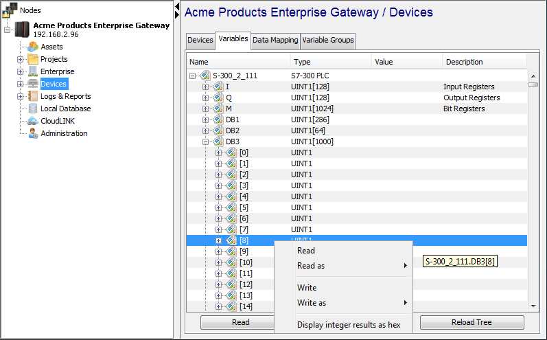
The following example demonstrates how to write a value to the FLOAT array defined in the Siemens PLC staring at address 8.0 using the Workbench.
Since the float array begins from array offset DB3[8],
follow these steps to write a value to that address in the
PLC.
- Right click on DB3[8] in the
Variables window of the Workbench.
This should display a context menu that lists all the
supported actions that can be performed on variable
DB3[8].
- Select the “Write as” option. A sub-menu displaying
all the supported types DB3[8] can be written as, is
displayed.
- Click on FLOAT4 (or REAL, depending on your
platform) and in the value text box enter 555.55 and
click OK.
- You should see the float value 555.55 displayed in
the Workbench Variables window at DB3[8].
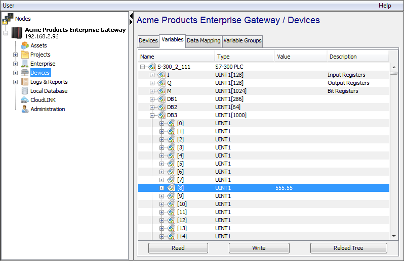
- Verify the value is written to the correct PLC
address through the STEP 7 software.
S7-200 V memory assignment
The S7-200 device provides a way to define V memory assignments in Data block pages using the STEP-7 software that will be enumerated by the Siemens S7 driver as a single DB1 data block.
In STEP-7, refer to the Help information for the
complete set of steps to define and download the Data Block
information. In the example below, the Data block pages
“USER1” and “USER2” have variables defined. The variables
from these Data block pages will be enumerated as a single
data block, “DB1” when the S7-200 device is Started.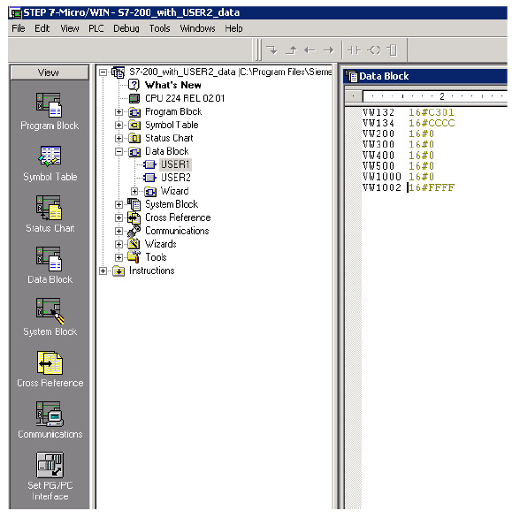
String data type
When accessing a Siemens PLC’s data blocks as a string data type, you need to be familiar with how strings are represented in the data blocks. The data type string represents a character string of up to 254 characters. A variable with the data type string occupies two additional bytes in memory to hold the maximum string length and the actual string length. The first byte holds the maximum string length (maximum number of characters), which can be up to 254. The second byte holds the actual string length. The character string then begins starting at the third byte.
For example, a string with a maximum length of 10 characters and a current character string of “hello” will be accessed in the PLC at data block DB500, starting at offset 0. This variable’s address is represented in the Variables window as DB500[0].
- The string’s maximum length of 10 occupies DB500[0]
- The string’s actual length of 5 occupies DB500[1]
- The string’s characters, starting with “h” occupies DB500[2], “e” at DB500[3], “l” at DB500[4], “l” at DB500[5] and “o” at DB500[6].
The Siemens S7 driver will write a string data type even if the maximum string length value is less than the number of characters being written. Care must be taken to read the string’s maximum length and ensure there is an adequate size before writing as a string data type. After the write, the maximum length byte will be set to the actual length value.
Supported device commands
The Siemens S7-200, S7-300 and S7-400 devices support
the following Device commands.
- Set PLC Mode: Run
- Set PLC Mode: Stop
When in the Started state, you can right click on a device to display its context menu and the list of Device commands that the device supports.
Supported device specific trigger actions
The Siemens S7-200, S7-300 and S7-400 devices support
the following device specific Trigger actions.
- Set PLC Mode: Run
- Set PLC Mode: Stop
These Trigger actions are enabled and selectable when you create a new Trigger and choose the Execute Device Command action under the Device group. The list of Started devices is selectable and then for a selected device, the available commands are listed.
Limitations
- The Siemens S7 driver does not support automatic enumeration of I/Q/M variables. These variable ranges are manually specified by the user. If the user specifies a range that is outside the physical range of these data points then a protocol error will be returned when attempting to access these variables. For more information, see Siemens S7 driver troubleshooting.
- The Siemens S7 driver does not support array write access for bit variables such as I/Q/M. If a count > 1 is specified when performing a write operation on bit variables a variable count overflow error is returned by the Siemens S7 driver. For more information, see Siemens S7 driver troubleshooting.
- For a TIMESTAMP data type, the daylight savings time and time zone information for the node is maintained for the current calendar year only. Accessing a TIMESTAMP outside of the current calendar year will use the information for the current year and may not return the expected value (e.g. a prior year that has a different daylight savings time start date).
- For a STRING data type the maximum supported length is 254 bytes.
Future revisions of the Siemens S7 driver might address the first three limitations as per requirements. The fourth limitation is in the communication protocol and cannot be addressed through any enhancements to the Siemens S7 driver.