Configuring the SmartIO
The deviceWISE Signal Interface Unit is configured by connecting it to a laptop or desktop unit on a point-to-point Ethernet network connection using the ‘LAN A’ network interface port. A web browser is then opened to address 10.1.1.101 to access the SmartIO configuration management interface.
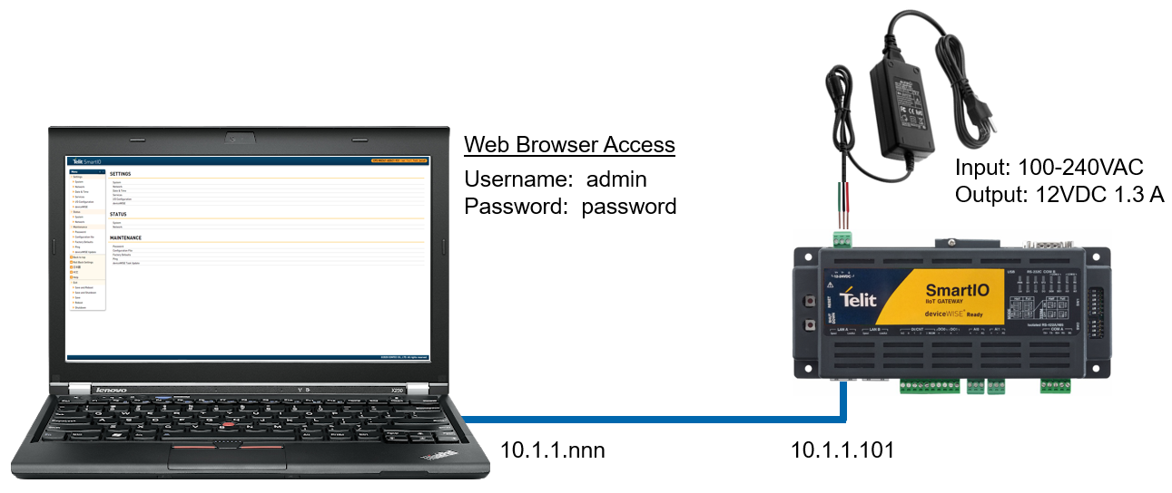
The following steps demonstrate how to setup and configure your deviceWISE SmartIO Signal Interface Unit to allow for connection and interaction within deviceWISE.
Your SmartIO is equipped with a default IP address of 10.1.1.101 and a subnet mask of 255.0.0.0. This IP address is used for the initial setup and configuration, though access from a building network is later preferred. Your SmartIO unit must have a unique IP address that is not used by any other devices on your network. This manual assumes your SmartIO unit has been properly networked and can be accessed from your deviceWISE Gateway.
- Connect the power supply to your SmartIO unit.
- Connect the unit and host controller by a straight cable.
- Set the IP address and network mask of the host controller so they belong to the same network as your SmartIO unit. (ex. 10.1.1.x and 255.0.0.0)
- Start a web browser and enter the IP address of your SmartIO unit in the address field. (Default 10.1.1.101)
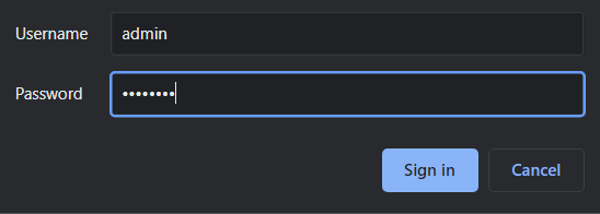
- When prompted for a login, enter the default username “admin” and password “password” to gain access. It is recommended that you change these credentials after configuration.
If a security screen appears, click to continue to the webpage. When using HTTP rather than HTTPS, this is not required. If you cannot connect to your SmartIO web panel, ensure that the host controller running the web browser is on the same network (see 6.1.2).
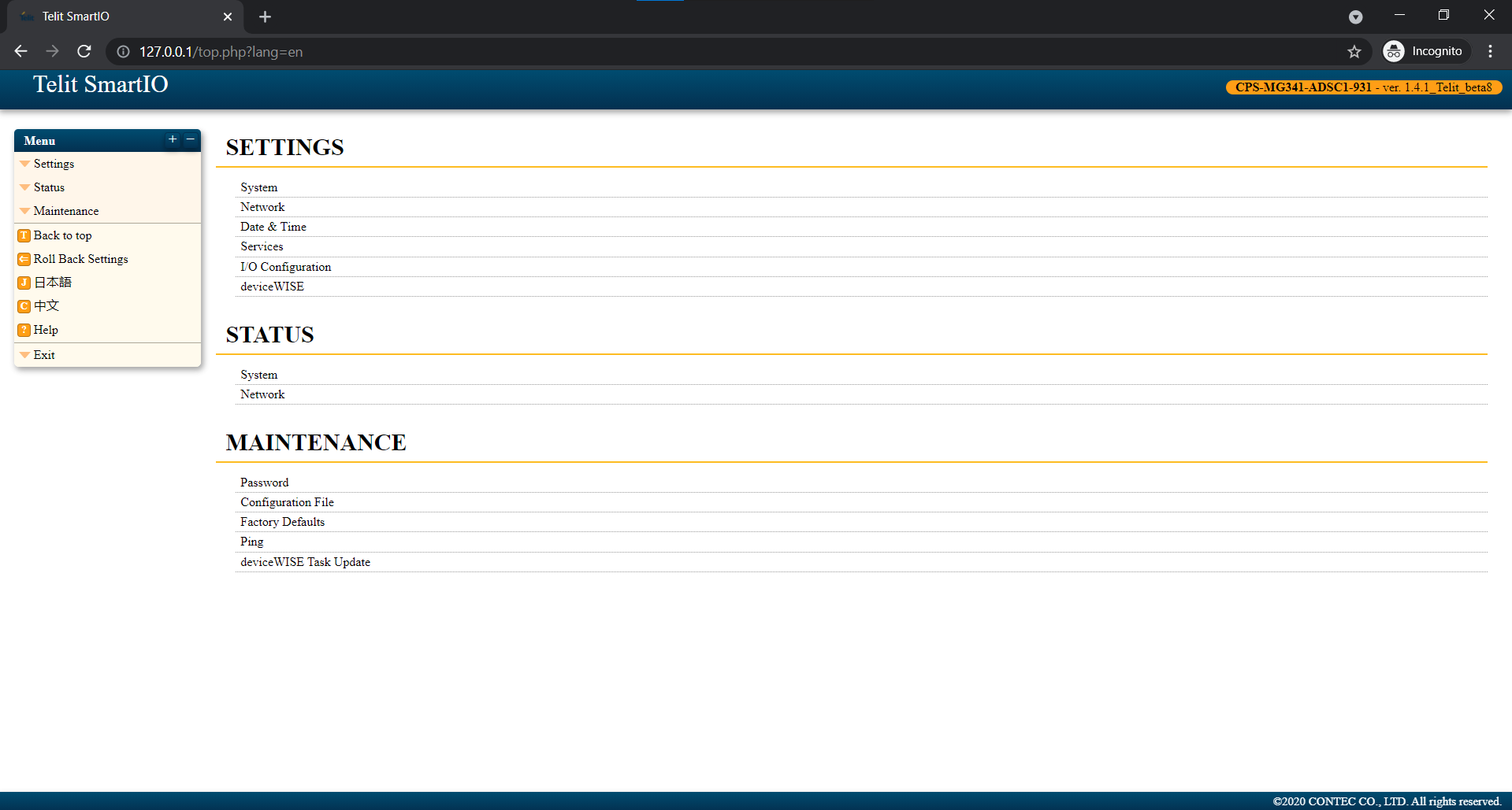
You should then be able to access the Telit SmartIO webpage where you can adjust settings and perform maintenance on your SmartIO unit. For the initial configuration, the network settings, date and time, I/O configuration, and deviceWISE settings will be updated depending on your network setup.
While it is important to keep one LAN port dedicated to a local ethernet connection between a host controller and your SmartIO unit as backup, adjusting your network settings can allow for deployments involving a larger building network.
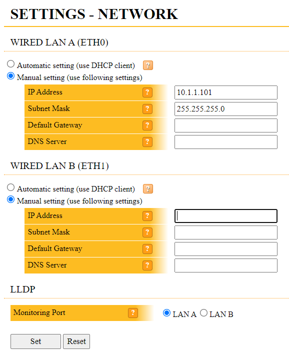
Click on the ‘Settings’ dropdown from the left side navigation panel. Then, select ‘Network’ to access your SmartIO unit’s network settings.
Under ‘WIRED LAN B (ETH1)’, enter the IP address, subnet mask, default gateway, and DNS server of your building network, if applicable, in their respective fields. ‘LAN A’ should remain default for guaranteed local access to your SmartIO unit. Click ‘Set’.
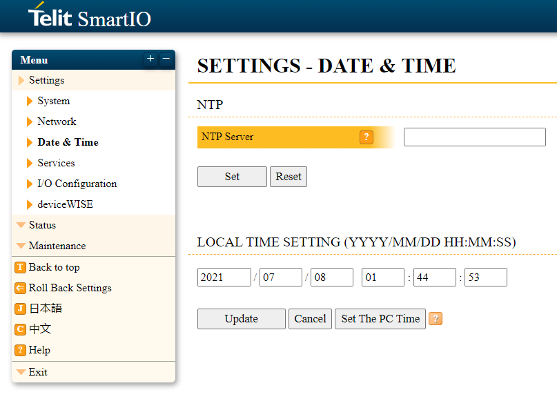
Under the ‘Settings’ dropdown again, locate and select ‘Date & Time’ to begin adjusting your date and time settings. Here you can manually set your local current time, sync the time with your computer by clicking ‘Set The PC Time’, or use an NTP server. Click ‘Update’.
Now that your network and time settings have been configured, your SmartIO unit must be pointed to deviceWISE in order to transmit signal and counter changes.
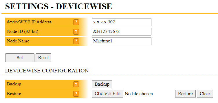
Navigate to ‘deviceWISE’ from under the ‘Settings’ dropdown menu on the left side panel. Here you must set the IP address of your deviceWISE Gateway. The default port 502 can be used for the communication between your SmartIO unit and deviceWISE.
Replace ‘x.x.x.x:502’ with the IP address of your deviceWISE Gateway. Ensure that this IP is on the same network set in ‘6.3. Network Settings’ and is reachable by your SmartIO unit. Keep the default Node ID ‘&H123456’ and name the node.
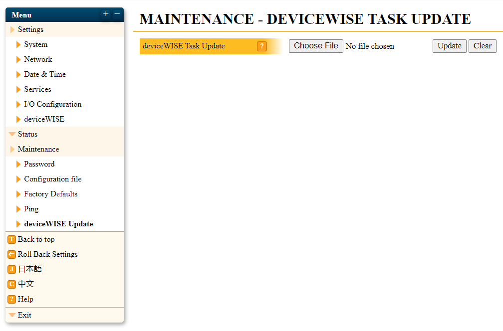
The ‘deviceWISE Task Update’ allows you to update your SmartIO unit.
Under the ‘Maintenance’ dropdown menu, select ‘deviceWISE Update’. Choose your update file by clicking ‘Choose File’ and begin the update by selecting ‘Update’.
ADSC1 CONFIGURATION
I/O Configuration
- Navigate to the ‘I/O Configuration’ page to begin adjusting the I/O settings on your SmartIO ADSC1 unit.
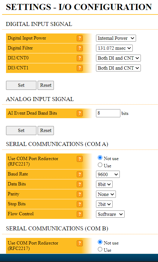
- Here, you have the ability to set a dead band on the analog input signal using the ‘AI Event Dead Band Bits’ option to control noise. This is performed entirely at the edge and prevents deviceWISE from receiving unnecessary traffic. To increase the dead band, up the number of bits to increase the mAmps required to trigger an update message and click ‘Set’. The table below illustrates the physical electrical signal or mA threshold that the signal must surpass for deviceWISE to receive an update message at each bit.
Every time settings are changed within your I/O configuration, such as ‘AI Event Dead Band Bits’, you must save and reboot your SmartIO unit for them to take effect. See ‘7.2. Save and Reboot’ for more information.
Bits AI Notification Event (+/1 Value) mAmps 0 1 0.0049 1 2 0.0098 2 4 0.0195 3 8 0.039 4 16 0.078 5 32 0.156 6 64 0.313 7 128 0.625 8 256 1.25 9 512 2.5 10 1024 5 11 2048 10 - Control noise on the digital input signal as well by using the ‘Digital Filter’ option.
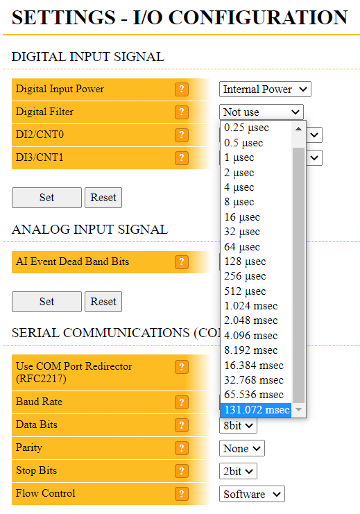
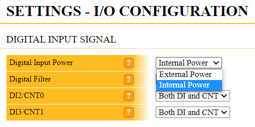
- ‘Digital Input Power’ allows you to choose between using ‘Internal Power’ or ‘External Power’ for the digital inputs. ‘DI2’ and ‘DI3’ can also function as ‘CNT0’ and ‘CNT1’ counter values. Note that counter values only increment when a DI becomes 1 from a state of 0.
Adjusting of your I/O configuration settings depends on your specific hardware setup.
Save and Reboot
Once these settings have been configured, it is important to save and reboot your SmartIO unit for all changes to take effect. Your unit should then be able to be accessed from your building network.
Under the ‘Exit’ dropdown menu, select ‘Save and Reboot’. Continue with the prompts to save and reboot your SmartIO unit.
DS11 CONFIGURATION
I/O Configuration
- Navigate to the ‘I/O Configuration’ page to begin adjusting the I/O settings on your SmartIO DS11 unit.
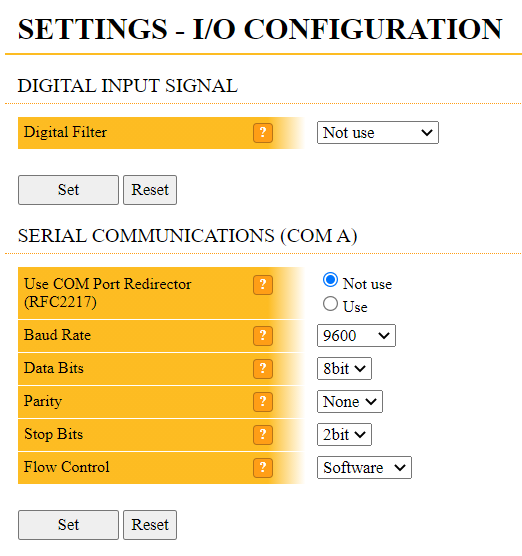
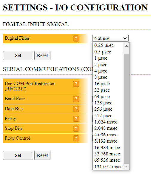
- Control noise on the digital input by using the ‘Digital Filter’ option.
Note that the adjusting of your I/O configuration settings depends on your specific hardware setup. Every time settings are changed within your I/O configuration, such as the ‘Digital Input Filter’, you must save and reboot your SmartIO unit for them to take effect. See ‘8.2. Save and Reboot’ for more information.
Save and Reboot
Once these settings have been configured, it is important to save and reboot your SmartIO unit for all changes to take effect. Your unit should then be able to be accessed from your building network.
Under the ‘Exit’ dropdown menu, select ‘Save and Reboot’. Continue with the prompts to save and reboot your SmartIO unit.