The Decode Binary Buffer action uses a
single input binary buffer to retrieve data values and then
writes the values to multiple output variables. The source
binary buffer variables, data types, offsets in the input
buffer, counts, intervals, lengths and special handling
options can be specified.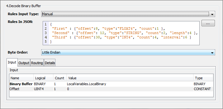
Parameter descriptions
The action provides these parameters:
| Parameter | Description |
|---|---|
| Rules Input Type | The options are:
|
| Rules in JSON | When Rules Input
Type is
Manual, this parameter
is used to specify the JSON description
of the variables to decode from a
binary buffer. Each variable is
specified as shown in the example
with:
|
| File | When Rules Input
Type is Staging
File, this parameter is used
to specify a file in the Staging
Browser area that contains the JSON
description of the variables to decode
from a binary buffer. This file is read when the trigger is edited. The description of the variables in the file is handled in the same manner as the Rules in JSON parameter. The file is only read when the trigger is edited, so changes to the file's content do not impact a started trigger's definition or function. To change a trigger's function, the trigger must be stopped, edited (the file is read) to make any necessary changes, and then restarted. |
| Byte Order | The options are:
|
 can be
used to display a
larger input area for
the JSON variable
description.
can be
used to display a
larger input area for
the JSON variable
description.Input tab
| Parameter | Description |
|---|---|
| Binary Buffer | Specifies the source binary buffer. |
| Offset | An optional offset used in addition
to each variable's offset value. This can be used, for example, when a variable length header in the source buffer needs to be accounted for. |
Output tab
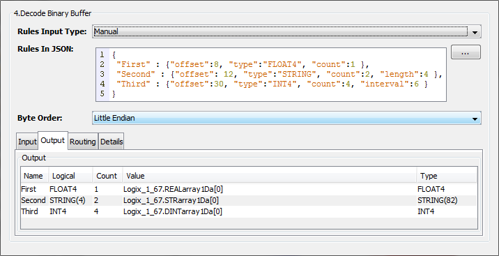
| Parameter | Description |
|---|---|
| Output map variables | The map variables identified in the
JSON variable description. Each variable in the JSON variable description will be added as a map variable row in the Output tab. In the Value column specify the destination variable. The variable can be trigger variable or device variable. |
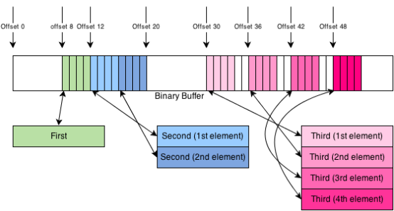
Decode Binary Buffer example
This example shows the JSON description of the variables and the placement of the data as it is read from the source binary buffer.
{
 "First" : {"offset":8, "type":"FLOAT4", "count":1 },
 "Second" : {"offset": 12, "type":"STRING", "count":2, "length":4 },
 "Third" : {"offset":30, "type":"INT4", "count":4, "interval":6 }
}
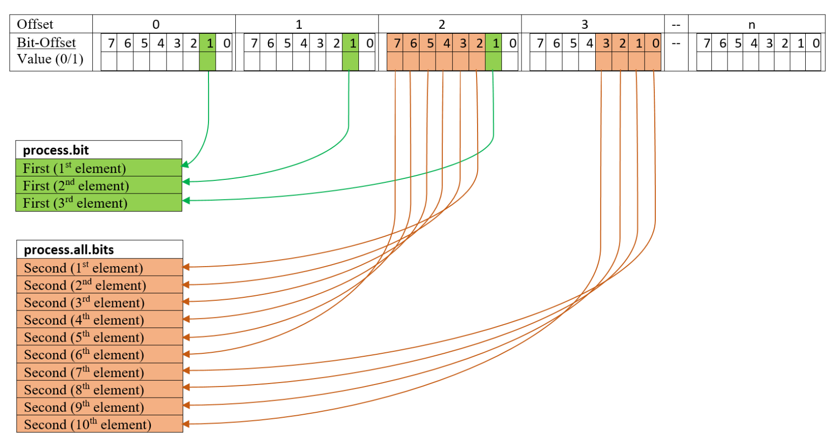
Decode Binary Buffer example using process.bit and process.all.bits
This example shows the JSON description of the variables and the placement of the data as it is read from the source binary buffer.
{
 "First" : {"offset":0, "type":"BOOL", "count":3, "bit_offset":1, "special":"process.bit" },
 "Second" : {"offset":2, "type":"BOOL", "count":10, "bit_offset":2, "special":"process.all.bits"}
}