Using the Workbench to define a FANUC device
The Workbench provides the view into a node's installation, configuration and resource definition. The Workbench also provides access and control over those resources.
A device is a resource that can represent a physical device, such as a programmable logic controller (PLC), an RF tag reader or a sensor. A device can also be defined in one node to represent a device that is defined and supported in another node. This allows your application solution to have access to devices and their data independent of their location or connectivity details.
To define a device that represents a FANUC CNC device, follow these steps:
- From the Workbench left pane, expand the node where
you want to define the device.
- Click on the Devices icon.
The Devices window appears as the right pane.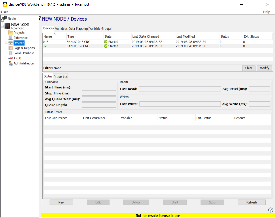
The Devices window provides a table format that lists the previously defined devices. - To define a new device,
click New at the bottom of the
pane.
The Device window appears. The available device types are determined by the device support that is installed in the node. - Use the Type down-arrow to select
the specific device under
the FANUC CNC group for the CPU you
wish to connect to. This list will vary based on your
node type.
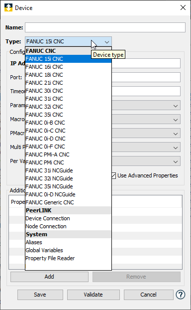
- The Device window changes to accommodate the
selected device type. The parameters displayed will be
modified based on the device type and possibly other
selections such as
Protocol and Use Advanced
Properties parameters:

- Define the FANUC CNC device using parameters
appropriate for the specific CNC type. The
parameters for each CNC type are defined in the
following sections.
- Click Validate to have the
parameters validated and to connect to the FANUC CNC device. If there is a problem connecting to the
FANUC CNC device, an error code will be
displayed.
- Click Save to save the device
definition. The device will appear in the Devices
window list of devices.
- You can now control the device (Start, Stop), access the device’s variables by using the Variables window, and build solutions that use the device’s resources.
FANUC CNC device properties
To define a FANUC CNC device, repeat steps 3 through 9. Set this new device’s parameters as follows:
|
Parameter |
Description |
|---|---|
| Name | Name for the FANUC CNC device. |
| Type | FANUC CNC model |
| IP Address | IP Address of the device. |
| Port | The port number used by the device. The default value is 8193. |
| Timeout | The timeout value to use when communicating with this device. This is entered in milliseconds. |
| Parameters | Enable parameter reads. True or False. |
| Parameter Write | Enable writing to parameters. True or False. |
| Macros | Enable macro reads. True or False. |
| Macro Write | Enable writing to macros. True or False. |
| PMacros | Enable Pmacro reads. True or False. |
| PMacro Write | Enable writing to Pmacros. True or False. CNC has separate controls on write to params. |
| Multi Path | Enable multiple paths. True or False. |
| Multi Path No. | The path number this device will connect with. |
| Per Variable Security | Select False to disable the allocation of additional memory to track User to Variable access for all Variables in this Device. Select True to enable this feature if required. For more information, see Setting up Read Write per device variable. |
| System Variables | A list of available System Variables Offset/Count. For example: 1000/50,3000/100,5000/1 would create System Variables 1000 - 1049, 3000 - 3099, and 5000. |