For Mitsubishi driver troubleshooting, the following section lists common tasks and problems and a list of Mitsubishi driver error codes.
The features and functions available in a node are controlled by the licenses that are installed in the node.
To verify that the Mitsubishi driver license is installed:
- From the Workbench left pane, expand the node whose
license you want to check, and then select
the Administration icon.
- From the Administration window, select
the Licenses tab.
- Select the appropriate license. Details of the
license appear on the tab.
- View the Features field to identify the device driver.
If you do not see the correct license, or if the license is expired, you must request a license from your license key provider.
For information on how to install a license, refer to System Administration > Licenses.
The number of active devices or connections exceed the total active device license count.The server or listener device will reject the connection attempt.
A system generated Alert will be displayed when the number of active device licenses in use exceeds a threshold percentage of the total active device licenses for the node. The Alert is cleared when the usage drops below the threshold percentage. For example, the system is currently using 90% of the available 200 device licenses.
An Exceptions Log message is inserted for the first connection rejection. For example, Device connection rejected due to insufficient device licenses.
For more information, see Licenses.
The device information on the Devices panel for a started server or listener device displays counts on its Attributes sub-tab:
- License In-Use
- License Rejected.
The Mitsubishi driver is not part of this node's installation. The Mitsubishi driver is installed as a separate package, separate from the base product installation.
You may be working with different levels of nodes, each with different levels of support for devices. Ensure that this node's installation is one with support for Mitsubishi CPUs.
For information on how to add the Mitsubishi driver package, refer to System Administration > Packages.
If you are encountering sporadic timeout errors, the CPU may be too busy servicing other requests, and the requests from the node are getting dropped by the CPU. The best recourse is to use the GX Developer, GX Works2 or FX Configurator software diagnostics to debug the problems.
The Validate option on the Device panel will attempt to make a TCP connection to the device at the defined location. It will also run some basic diagnostics to determine if this is indeed a Mitsubishi FX device. The Start option on the Device List panel will perform these steps but also enumerate the data tags defined on the device. A device that can validate but cannot be started is the result of a failure with the tag enumeration step. The best recourse is to ensure the validity of the tag definition using the GX Developer or FX Configurator software.
The connection from the Mitsubishi driver to the
Mitsubishi CPU device can become "stale" after a period of
time when no reads or writes are issued for the Mitsubishi
CPU device.
When the first read or write is issued after this period of
time, the connection between the Mitsubishi driver and the
Mitsubishi CPU device is no longer valid and the attempted
read or write is marked as a communication failure. When
this happens, the deviceWISE device is placed into a
Disabled state. The devceWISE device successfully recovers
to a Started state as part of the periodic device recovery
logic.
To keep the connection from going stale when there are periods of no reads or writes issued by the application's triggers, the Keep Alive parameter in the deviceWISE device definition can be used to have the Mitsubishi driver send a periodic heart beat message. The default value for the Keep Alive parameter is 180 seconds.
The device associated with either an FX or an A Series CPU may experience a problem in which it becomes disabled due to a network communication error encountered by the CPU. In these instances the driver will periodically attempt to re-establish communication by setting up a new TCP connection with the CPU. Tests with these models have shown that the CPU doesn’t properly disconnect or delete the earlier connection and will reject any new connection requests. The only solution is to restart the CPU, which will forcibly delete the old TCP connection to the node and clear the way for a new connection to be made.
The device associated with a GOT may experience a problem in which it becomes disabled due to a network communication error encountered by the GOT. In these instances the driver will periodically attempt to re-establish communication by setting up a new connection with the GOT. Tests have shown the GOT doesn’t properly disconnect or delete the earlier connection and will reject any new connection requests. The only solution is to restart the GOT, which will forcibly delete the old connection to the node and clear the way for a new connection to be made.
The A Series PLC’s have a limitation that prohibits having more than one external connection active at any time. Locations that have multiple nodes will be affected in that even though a device can be defined for an A series CPU at a specific IP address on every node, only one of those devices can be in a started state at any one time. For example nodes A and B both have a device object defined associated with the A Series CPU at IP address 192.168.1.100. The device defined on node A has been started and is shown in the Workbench Device Panel as being in a Started state. Attempts to start this device on node B will fail because the A Series CPU will support only one active external connection at a time. This limitation is somewhat less restrictive with an FX series CPU in that tests have shown that these CPU’s will support up to three concurrent active external connections since different ports can be specified in the PLC configuration.
The driver allows the user to read and write data to the points in the X (Input Relay) and Y (Output Relay) device types. Though allowed, it is incumbent upon the user to know which of the Input Relay and Output Relay points can be safely written to. This information can be determined using the GX Developer or GX Works2 software's PLC Parameter->IO Assignment panel.
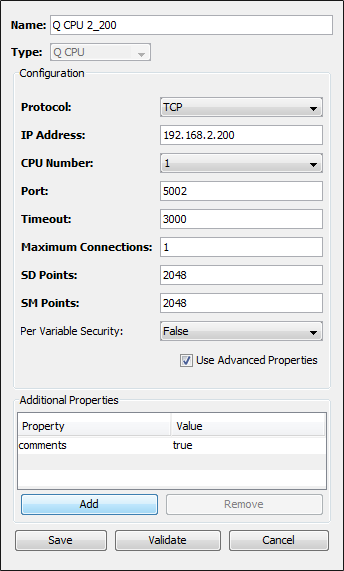
Through GxWorks, you can assign alias names to device
locations on the Q CPU PLC. Additionally comments can be
added to aid in the identification of the use of specific
device locations. During the device start phase, the
Mitsubishi driver will not obtain this information unless
it is specifically asked for in the device definition. This
is done by adding an additional property named
"comments" to the device. This property
will have a value of "true". The image
below shows what the definition panel will look like when
the additional "comments" property is
added to a Mitsubishi Q CPU device.
A value of True might also be displayed in this field, even though True is not a selection in the list. The Filter field list of options was modified beginning with the 3.0.0 release of Mitsubishi driver. This release allows for a third filter value, MC Write. Backward compatibility is built into this change to allow triggers that were developed under previous driver releases to continue to work. Editing one of these triggers may be confusing as the Filter value of False or True will continue to be shown, even though the values in the Filter list are Data Length, Word Value, and MC Write. For backward compatibility, a value of False will perform as if the Data Length filter was selected. A value of True will perform as if the Word Value filter was selected.
Reduce Maximum Connections setting to 4 or less. Some Mitsubishi QCPU models cannot use settings higher than 4.
Driver sends data packets in 4E frame format, if the Maximum Pending Packets value is greater than 1. Some HW or FW versions does not support 4E frame format. Make sure the device supports the 4E frame format.
This section describes the error codes that you might encounter when using the Mitsubishi driver.
These error codes are available from the Devices window in the Extended Status column. The error codes are also referenced in the Exceptions Log.
When the system experiences an abnormal condition (such as a device failure, disconnect from a controller, or software error), an error code and extended error code are recorded in the Exceptions Log.
In the Devices window, the Status column will always be a generic error code that can tell you if the error is a communication error, a data error, or some other internal device error. The Extended Status column provides the error code from the driver. The driver error codes will be shown as decimal values, even though the Mitsubishi driver returns them in a hexadecimal format. A listing of some of the Mitsubishi specific error codes that might be encountered by the driver are shown below. Please consult the Mitsubishi documentation for a complete list of error codes and suggested corrective actions.
| Extended Status code | Error name | Action |
|---|---|---|
| 0x11 | Communication mode error | Attempt to execute the process again. Perform diagnostic check of network to ensure device and node can communicate. |
| 0x1B | Remote Error | Check the Mitsubishi device to see if the CPU Err light is on or the PROG light is flashing. |
| 0x50 | Command code are not within the specifications | Internal program error occurred |
| 0x54 | ASCII code data could not be converted to binary representation | Internal error occurred when sending a message to the device. |
| 0x56 | Device designation is incorrect | Correct the device designation |
| 0x57 | Maximum number of connections has been exceeded | Increase the number of designated points |
| 0x58 | A word device has been designated in a bit device command | Select the correct device for the command being performed |
| 0x5B | Communication error between the Mitsubishi device and the node | Check all connections, ensure the device can be reached from the node |
| 0x60 | Communication time between the device and the node has timed out | Increase the monitoring timer value |