The Mitsubishi Listener is a unique device type in that it does not represent a physical Mitsubishi PLC. Instead, this “Listener” device, when started, activates a process on the node that will listen for unsolicited BUFSND messages sent from Mitsubishi PLCs. The ladder logic running on the Mitsubishi PLCs must be configured to route the BUFSND message to the node. Beginning with the 3.0.0 release of the Mitsubishi driver, there are two types of Mitsubishi Listener that can be defined, the Passive Listener and the Active Listener. The Passive Listener is a continuation of previous implementations of the Mitsubishi Listener. The Passive Listener will create a TCP socket and accept connections from any Mitsubishi PLC. With the Active Listener, a set of Mitsubishi PLCs are defined, and the Listener will establish the TCP socket communication with each of the PLCs. The establishment of the TCP socket communication will be done when the Active Listener is Started. Stopping the Listener will close the communication between the Listener and the PLC. The Active Listener will attempt to create the socket connection every 30 seconds in a situation where a communication link cannot be immediately established with the PLC or if a PLC that had been connected goes offline. The sending of the BUFSND messages from the PLC to the Listener will remain the same, whether the Listener is in Passive or Active mode.
To define a device that represents a Mitsubishi Listener device, follow these steps:
- From the Workbench left pane, expand the node where
you want to define the device.
- Select the Devices icon.
The Devices window appears as the right pane.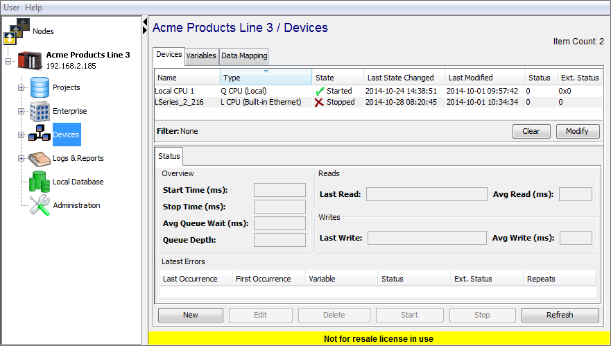
The Devices window provides a table format that lists the previously defined devices. - To define a new device,
select New at the bottom of the
pane.
The Device window appears. The available device types are determined by the device support that is installed in this node. - Use the Type down-arrow, to
select Mitsubishi Listener under
the Mitsubishi group.

- The Device window changes to accommodate the
Mitsubishi Listener device type.
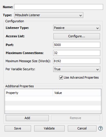
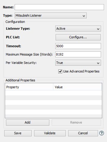
- To define a device that represents a Mitsubishi
Listener, set this new device’s parameters as
follows:
Parameter Description Name Enter a name for the Mitsubishi Listener device. Type Select Mitsubishi Listener. Listener Type This field determines whether the connection between the Mitsubishi Listener and the PLC will be established by the Listener or the PLC. The default value, Passive, indicates that the Mitsubishi Listener will create a socket and wait for connections from any Mitsubishi PLC. The Active option allows the definition of specific PLCs that the Listener will connect with, when it is started. In both scenarios the logic on the PLC will be updated to send BUFSND messages to the Listener. Access List This field will be shown only if the Passive option has been selected in the Listener Type field. Selecting the  button will display the
Filtered
Addresses pop-up
window to define the access
list used by the Listener. The
access list defines what IP
addresses are allowed to
connect and send unsolicited
messages to this node. This is
done by either granting or
denying access privileges to
specific IP addresses or to
entire IP subnets. Care must be
taken when defining entries in
the list to ensure that the
Listener works properly and
receives messages from intended
PLCs.
button will display the
Filtered
Addresses pop-up
window to define the access
list used by the Listener. The
access list defines what IP
addresses are allowed to
connect and send unsolicited
messages to this node. This is
done by either granting or
denying access privileges to
specific IP addresses or to
entire IP subnets. Care must be
taken when defining entries in
the list to ensure that the
Listener works properly and
receives messages from intended
PLCs.PLC List This field will be shown only if the Active option has been selected in the Listener Type field. Selecting the
button will display the
Endpoints pop-up window, which
is used to define the location
of the PLCs that will send
messages to the Listener. The
parameters found on the
Endpoints
pop-up window are defined in
the next section.Port This field will be shown only if the Passive option has been selected in theListener Type field.Enter the port number to be used by the Listener device. The default port value is 5000. This will be the port on the node that the Listener will create to accept connections from a Mitsubishi PLC. Maximum Connections This field will be shown only if the Passive option has been selected in theListener Type field.This is the maximum number of PLC connections that the Listener is allowed to service at the same time. Care should be taken to create a reasonable limit based on the number of PLCs that will be sending BUFSND messages to the node. The default value is 32. Maximum Message Size Enter the maximum size of the message that the Listener will process. This value is word based, where a word is a two byte entity. The default value is 8192 words, or 16384 bytes. Messages that exceed this limit will be refused by the Listener. Per Variable Security Select False to disable the allocation of additional memory to track User to Variable access for all Variables in this Device. Select True to enable this feature if required. For more information, see Setting up Read Write per device variable. - The following fields are displayed in the
Endpoints pop-up window.
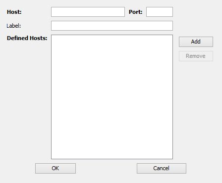
Parameter Description Host Enter the IP Address or the Host Name of the Mitsubishi PLC that will send the BUFSND messages. Port The TCP port on the Mitsubishi PLC that the Active Listener will establish communications. Label An optional text field that can be used to provide a description identifying the Mitsubishi PLC. This value will be passed to the Mitsubishi (BUFSND) trigger where it can be used to identify the PLC sending the message. Add Button This button is used to add a defined Mitsubishi PLC to the Defined Hosts list. Defined Hosts This list will contain entries of the Mitsubishi PLCs that the Active Listener will establish TCP socket communications with. Remove Button This button is used to remove a Mitsubishi PLC from the list of hosts that the Active Listener will communicate with. The button will be disabled until an entry is selected. - Select Validate to have the
parameters validated. If there is a problem, an error
code will be displayed.
- Select Save to save the device
definition. The device will appear in the Devices
window list of devices.
- You can now control the device (Start, Stop), access the device’s variables by using the Variables window, and build solutions that use the device’s resources.