Using the Workbench to define a Modbus device
The Workbench provides the view into a node's installation, configuration and resource definition. The Workbench also provides access and control over those resources.
A device is a resource that represents a physical device, such as a programmable logic controller (PLC), an RF tag reader or a sensor. A device can also be defined in one node to represent a device that is defined and supported in another node. This allows your application solution to have access to devices and their data independent of their location or connectivity details.
It is possible to define the following devices with the Modbus driver:
- Devices that implement the Modbus messaging service and are accessible through TCP/IP
- Devices that implement the Modbus messaging service that are connected serially over a RS-232 or RS-485 connection
- These devices can provide Read only or Read/Write support to a combination of the following Modbus tables:
- Coils
- Discrete Inputs
- Input Registers
- Holding Registers
To define a device that represents a Modbus device, follow these steps:
- From the Workbench left pane, expand the node where you want to define the Modbus device.
- Click Devices to display the Devices panel, right-click on Devices and then select New.
Alternatively click New at the bottom of the Devices panel.
The Device window appears. - Enter the name of the device. The device name can be up to 64 characters and include letters, numbers, and the underscore character. Spaces are allowed.
- Click Type down-arrow and select Modbus Device under the Modbus category.
The available device types are determined by the driver packages that are installed on the node.
Using the generic Modbus Device type, specify the size for each of the four Modbus data block regions, Coils, Discrete Inputs, Input Registers, and Holding Registers.
The Device window changes to accommodate the selected device type. For this example the generic Modbus Device.
The generic Modbus Device type lets you define a device that represents a physical device that supports the Modbus protocol. In addition, the generic Modbus Device is accessible through either an Ethernet TCP or serial connection. There might also be vendor specific Modbus devices available under the Modbus category. These selections contain predefined data block information for a specific Modbus device. - To define a device that represents a Modbus device, set this new device's parameters as described in the following sections for Connection Type is set to Ethernet or Connection Type is set to RS-232 or RS-485:
The following shows a portion of the Device window when Type is set to Modbus Device and Connection Type is set to Ethernet.Parameters for Connection Type = Ethernet Parameters for Connection Type = RS-232 or RS-485 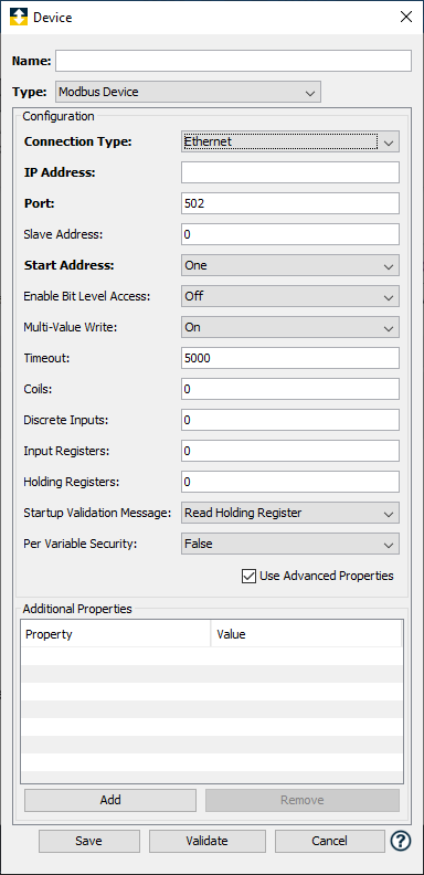
Parameter Description Connection Type 
When you select Ethernet, the parameters under Configuration on the Device window change to accommodate Ethernet communication beginning with the IP address.IP address Enter the IP address of the Modbus enabled device. Port Enter the port number used by the Modbus enabled device. The default is 502. Slave Address The default value of zero should be used if connecting directly to a Modbus device. If the IP address is to a gateway device, then type a numeric value, between 1 and 247, that identifies the device connected on the sub-network behind the bridge or the gateway. Start Address Select if you would like the variable array offset to begin with a 1 (the default for version 2.4 of the Modbus driver) or zero (the default for all versions prior to 2.4). This setting affects the visual display of a variable and its reference from within a trigger. Physical device level references are zero based. Enable Bit Level Access Enables Bit Access (Nested Bool) for Holding Registers. The default value is off. Function Code 22
Write the Bits using the Function Code 22 (0x16) which is the safe mode to write bits. Some PLCs does not support this function code.Read Modify Write
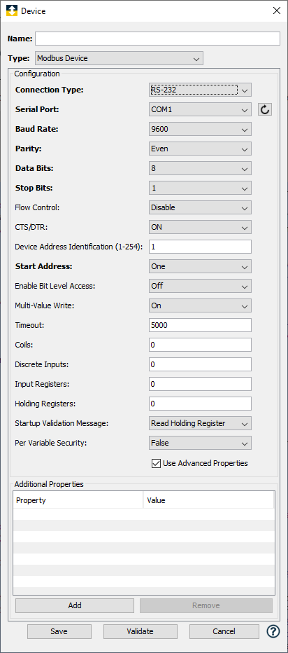
Use this option when Function Code 22 is not supported and this option is not the Safe option. Data might change while Reading or modifying (the bits as per the request) or while writing (by other devices accessing the same data). This mode is not recommended.Multi-Value Write Select if you would like the driver to write multiple variables with one request. The default value is On. Having this feature turned On will result in dramatically improved performance for implementations that change values on a Modbus device. The only time this should be set to Off is if the physical Modbus device does not support the Multi-Write commands (0x0f and 0x10). Timeout This is the timeout value in milliseconds to use when communicating with this device. The default value is 5000 (5 seconds). Coils The number of Bits needed to represent the Coils defined on the Modbus enabled device. Refer to the configuration software or product data sheet supplied by the device manufacturer for the exact size of this table. Discrete Inputs The number of Bits needed to represent the Discrete Inputs defined on the Modbus enabled device. Refer to the configuration software or product data sheet supplied by the device manufacturer for the exact size of this table. Input Registers The number of Words needed to represent the Input Registers defined on the Modbus enabled device. Refer to the configuration software or product data sheet supplied by the device manufacturer for the exact size of this table. Holding Registers The number of Words needed to represent the Holding Registers defined on the Modbus enabled device. Refer to the configuration software or product data sheet supplied by the device manufacturer for the exact size of this table. Startup Validation Message When the device is started this message is send by the driver to the physical device located at the specified IP address. The message is sent to determine if the physical device is online and supports the Modbus protocol. There are three options, Read Holding Register, Read Coil, or None, which is the default value. The first element in the register area will be read if either Read Holding Register or Read Coil is selected. The driver will assume the device supports the Modbus protocol and is online, if the None option is selected. Per Variable Security Select False to disable the allocation of additional memory to track user to variable access for all variables in this Modbus enabled device. Select True to enable this feature if required. For more information, see Setting up Read Write per device variable. Parameters for Connection Type = RS-232 or RS-485 Connection Type 
When you select either RS-232, or RS-485, the parameters change to accommodate serial communication beginning with the serial port.Serial Port The port through which the serial connection to the Modbus RTU device is being made. This list will be generated to match the operating system for the node. For example, the list will contain the COM ports for Microsoft Windows operating systems, //dev/tty ports for Linux operating systems, and so forth. Baud Rate The baud rate defined for the port. The default value is 9600. Parity The parity setting. The default value is Even. Data Bits The data bit value. The default value is 8. Stop Bits The number of stop bits. The default value is 1. Flow Control The flow control setting. The default value is Disabled. CTS/DTR Used for hardware flow control. The default value is ON. Device Address Identification (1-254) The device identification number assigned to the desired device. This allows for the identification of a specific device in an implementation where multiple devices have been daisy-chained together. The default value is 1, which should be used for a single device. - Click Validate to validate the parameters and to connect to the Modbus device. If there are problems connecting to the Modbus device, an error code will be displayed.
- Click Save to save the device definition. The device will appear in the Devices window list of devices.
You will now be able to control the device (Start, Stop), access the device's variables by using the Variables window, and build solutions that use the device's resources.
Vendor device definition files
When you specify Modbus Device from the Type parameter on the Device window, you must supply information about the data blocks defined on the physical device. Data blocks are the number of Coils, Discrete Inputs, Input Registers, and Holding Registers defined on the device. The Modbus driver might also ship with device definition files that are specific to a Modbus enabled vendor device. The device definition file will contain a description of the data blocks for a specific Modbus enabled device. The presence of these files will be indicated from the Type parameter on the Device window. Use the Type down-arrow to display the full list of Modbus enabled devices that are supported by the driver.
The example shows the generic Modbus
Device and three other device types that correspond to vendor specific Modbus devices. Selecting any one of these device types will bring with it the unique specifications associated with the vendor's definition of the Modbus data blocks. You will be responsible for defining how the device is connected to the node using either an Ethernet, RS-232, or RS-485 connection. You must also provide the connection specific settings such as IP address for Ethernet, or Baud Rate for RS-232 and RS-485. The data block definitions associated with the vendor's Modbus device are automatically set and cannot be modified.
The following shows an example of the Device window for a vendor specific Modbus device. The difference between the vendor specific Modbus device window and the generic Modbus Device is the vendor specific window does not allow for the input of data block sizes.
Using XML to create a vendor specific Modbus device
definition provides details on how a vendor specific XML file can be created to define a specific Modbus device implementation.