For Omron driver troubleshooting, the following section lists common tasks and problems and provides a reference for Omron driver error codes.
The features and functions available in a node are controlled by the licenses that are installed in the node.
To verify that the Omron driver license is installed:
- From the Workbench left pane, expand the node whose license you want to check, and then select the Administration icon.
- From the Administration window, select the Licenses tab.
- Select the appropriate license. Details of the license appear on the tab.
- View the Features field to identify the device driver.
If you do not see the correct license, or if the license is expired, you must request a license from your license key provider.
For information on how to install a license, refer to System Administration > Licenses.
The number of active devices or connections exceed the total active device license count.The server or listener device will reject the connection attempt.
A system generated Alert will be displayed when the number of active device licenses in use exceeds a threshold percentage of the total active device licenses for the node. The Alert is cleared when the usage drops below the threshold percentage. For example, the system is currently using 90% of the available 200 device licenses.
An Exceptions Log message is inserted for the first connection rejection. For example, Device connection rejected due to insufficient device licenses.
For more information, see Licenses.
The device information on the Devices panel for a started server or listener device displays counts on its Attributes sub-tab:
- License In-Use
- License Rejected.
The Omron driver is not part of this node's installation. The Omron driver is installed as a separate package, separate from the base product installation.
You may be working with different levels of nodes, each with different levels of support for devices. Ensure that this node's installation is one with support for Omron CPUs.
For information on how to add the Omron driver package, refer to System Administration > Packages.
The Omron CS, CJ and CP PLCs need to be configured using the CX-Programmer software, while the Omron NJ PLC is configured using Omron's Sysmac Studio. The complete description of this configuration is beyond the scope of this document. Ensure that the Conversion setting and the IP address table in the network settings are correctly configured for your network setup.
This section describes the error codes that you might
encounter when using the Omron driver.
These error codes are available from the
Devices window on the Extended
Status column. The error codes are also referenced
in the Exceptions Log.
When the system experiences an abnormal condition (such as a device failure, disconnect from a controller, or software error), an error code and extended error code are recorded in the Exceptions Log.
In the Devices window, the Status column will always be a generic error code that can tell you if the error is a communication error, a data error, or some other internal device error. The Extended Status column provides the error code from the driver. These error codes can be basic runtime error codes or specific to the Omron driver.
Refer to the FINS Reference manual (page 109) for detailed protocol-specific error codes.
Triggers are not firing upon receipt of the Omron CIP unsolicited messages
At times it may appear that the Omron driver is not processing the unsolicited messages that the Omron NJ PLC is sending. Remember that there is a one-to-one relationship between an unsolicited message defined on an Omron NJ PLC and a trigger. If you find the unsolicited messages being sent are not being processed by your trigger, check the following areas to locate the problem:
- Verify that you have defined an Omron CIP Listener device on your node. Ensure that the Omron CIP Listener device is in a Started state.
- Verify that the Route Path value on the CIPUCMMSEND or the CIPUCMMWRITE message defined on the Omron NJ PLC is referencing the IP address of the node.
- Ensure that the Service Code, Class, Instance, and Attribute values entered for a CIPUCMMSEND message matches the Service Code, Class, Instance, and Attribute values defined in the Omron (CIP) event trigger. These fields must match exactly.
- Ensure that the DstDat value defined for a CIPUCMMWRITE message matches the Destination value defined in the Omron (CIP) event trigger. Alternately, use the '*' wildcard value in the Destination field in the trigger.
- Verify that the Size value specified in the CIPUCMMSEND message equals the Input Length value specified in the trigger definition. Note that the Size value is a number of elements, while the Input Length value is the size of the data in bytes. You must calculate the number of bytes by multiplying the bytes needed for the data type selected, by the number of those elements. For example if expecting 10 variables of data type INT4, the Input Length value should be 40.
- Verify that the Size value specified in the CIPUCMMWRITE message equals the Element Count value specified in the trigger definition. Note that the Size value is a number of elements so these values should match exactly.
- Verify that the unsolicited message is indeed being sent by the Omron NJ PLC. This can be verified by inspecting the Error and ErrorID fields in the message block on the Omron NJ PLC.
- Turn on the trigger reporting option in the trigger's definition to see if the trigger is executed and the raw format of the associated data is present.
The default port used by the Omron CIP Listener device is 44818. This is the default CIP port and is used by other CIP enabled products, such as the Rockwell RSLinx software and also the Rockwell Unsolicited Logix Listener.
If the RSLinx software is on the same Windows machine as the Enterprise Gateway for Windows node - and the RSLinx software is started - this port conflict will prevent the Omron CIP Listener device from starting. In turn, this will prevent the listener from receiving unsolicited messages from Omron NJ PLCs.
To remove the port conflict with the Rockwell RSLinx software
- Do not have the Rockwell RSLinx software installed on the same machine as the Omron CIP Listener.
- If the Rockwell RSLinx software is installed on the same machine, ensure that it is not running.
- If the Rockwell RSLinx software must be installed and running on the same machine as the Omron CIP Listener, modify the port defined for the Omron CIP Listener. This will also require a change to the ladder logic on the Omron NJ PLC.
If a Rockwell Unsolicited Logix Listener device is started and using the same port as the Omron CIP Listener, the Omron CIP Listener will not be able to start. In this scenario messages sent by Omron NJ PLCs would be processed by the Rockwell Unsolicited Logix Listener, since the format of the CIP protocol message is implemented in the same fashion by both PLC Vendors.
If you would like to use the Rockwell Unsolicited Logix Listener and the Omron CIP Listener on the same machine.
- Ensure that the two listeners are using separate ports.
- Modify the Message command in the ladder logic on both the Rockwell ControlLogix PLC and the Omron NJ PLC to send their messages using the appropriate port.
The CIPUCMMWRITE message allows the user to send all of the data within a structure to a trigger. The trigger will receive this data as a BINARY data type variable. The Omron NJ PLC aligns the data, using null (0x00) bytes to separate elements within the structure. This can best be described using the following example.
This image shows the values for each member in a
structure named TESTSTRUCTURE_X_2. This structure will be
sent to the node as the data portion of a CIPUCMMWRITE
message.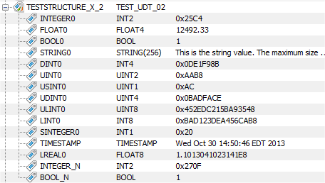
A trigger report is generated for the trigger when it is
executed. The raw data layout of the structure data, as
received by the trigger, is shown in the following trigger
report image.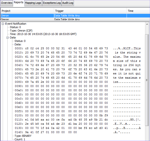
The first two bytes are used internally by the runtime and can be ignored. The next two bytes, 0xc4 and 0x25, are associated with the first element in the Structure, named INTEGER0. Notice there are two bytes, 0x00 and 0x00, that are pad bytes and can be ignored, prior to the bytes associated with the element named FLOAT0. There are four bytes associated with this variable. The byte associated with the next element named BOOL0, has a value of 1, and is followed by an additional pad byte 0x00. This pad byte precedes the first byte of the string named STRING0. The value of this byte is 0x54. Notice that the entire contents of the string, all 256 bytes, are sent to the trigger. There are two pad bytes after the 256th byte of the STRING0 element. The first byte of the next element named DINT0 is 0x8b.