The Workbench provides the view into a node's installation, configuration and resource definition. The Workbench also provides access and control over those resources.
A device is a resource that can represent a physical device, such as an Emerson ROC800-Series controller, an RF tag reader or a sensor. A device can also be defined in one node to represent a device that is defined and supported in another node. This allows your application solution to have access to devices and their data independent of their location or connectivity details.
The following devices are supported by the ROC Plus driver:
- Emerson ROC827
- Emerson ROC809
Defining a ROC Plus device
To define a device that represents an Emerson
ROC800-Series controller, follow these steps:
- From the Workbench left pane, expand the node where
you want to define the device.
- Select the Devices icon. The
Devices window appears as the right pane.

The Devices window provides a table format that lists the previously defined devices. - To define a new device, select New
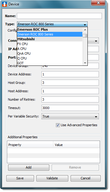
at the bottom of the pane. The Device window appears.
The available device types are determined by the device
support that is installed in this node.
- Use the Type down-arrow, to select
a device type under the Emerson ROC
Plus group.
- The Device window changes to accommodate the
selected ROC Plus device type.
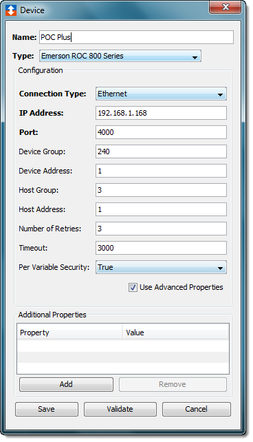
- To define a device that represents an Emerson
ROC800-Series controller, set this new device’s
parameters as follows:
| Parameter | Description |
|---|---|
| Name | Enter a name for the Emerson ROC800-Series controller. |
| Connection Type | Select the communication connection
type that will be used to communicate
with the ROC800-Series
controller.
|
| IP Address | Enter the IP Address of the
ROC800-Series controller. This option will be displayed if the Ethernet connection type option is selected. |
| Port | Specify the TCP port on which to
establish communication with the
ROC800-Series controller. The default
value of 4000 should be used in most
cases. This option will be displayed if the Ethernet connection type option is selected. |
| Serial Port | The port through which the serial
connection to the ROC800-Series
controller is being made. This list will be generated to match the operating system for the node. For example, the list will contain the COM ports for Microsoft Windows operating systems, //dev/tty ports for Linux operating systems. This option will be displayed if the RS-232 connection type option is selected. |
| Baud Rate | The baud rate defined for the port.
The default value is 9600. This option will be displayed if the RS-232 connection type option is selected. |
| Parity | The parity setting. The default
value is None. This option will be displayed if the RS-232 connection type option is selected. |
| Data Bits | The data bit value. The default
value is 8. This option will be displayed if the RS-232 connection type option is selected. |
| Stop Bits | The number of stop bits. The default
value is 1. This option will be displayed if the RS-232 connection type option is selected. |
| Flow Control | The flow control setting. The
default value is Disable. This option will be displayed if the RS-232 connection type option is selected. |
| Device Group | The Grouping ID of the ROC800-Series
controller. Refer to your ROCLink 800 configuration software for this value. |
| Device Address | The unique address value for the
ROC800-Series controller within the
Device Group. Refer to your ROCLink 800 Configuration software for this value. |
| Host Group | The Grouping ID that will be associated with the ROC Plus driver. This must be the same value as the Device Group value. |
| Host Address | A unique address value, within the Host Group, assigned to this ROC Plus device. |
| Number of Retries | The number of times the ROC Plus driver will attempt to reissue a command that has timed out. The ROC Plus device will disable if the ROC800-Series controller does not reply to a command once the number of retries has been reached. |
| Timeout | Enter the timeout value to use when communicating with this device. This is entered in milliseconds. |
| Per Variable Security | Select False to disable the allocation of additional memory to track User to Variable access for all Variables in this Device. Select True to enable this feature if required. For more information, see Setting up Read Write per device variable. |