Data Table Write
Use this section while Defining a trigger for a Rockwell unsolicited message when you select Data Table Write command.
Unsolicited Logix Listener Data Table Write Command payload parameters
The following parameters are displayed on the trigger
definition panel when the Data Table Write command is
selected. The values entered in these parameters must match
the values that were entered while defining the unsolicited message in the RSLogix 5000 software.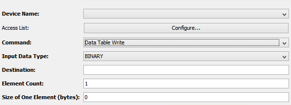
| Parameter | Description |
|---|---|
| Destination | The value here must match the value entered in the Destination Element parameter of the CIP Data Table Write message defined on the Logix PLC. |
| Element Count | The number of elements that matches the data the message is expecting. |
| Input Data Type | Select the data type that matches the data the message is expecting. |
| Size of One Element (bytes) | This field is displayed if the Binary or the String option is selected in the Input Data Type field. |
- The Destination and Element Count parameters are
used by the Rockwell driver as values to compare
against a received Data Table Write unsolicited
message. A trigger that matches all of these parameters
will be run. The message will be dropped if there is no
match.
- Entering the * character as the value in the Destination field indicates that the trigger will be used as a default trigger, meaning it will execute in case there are no other triggers that match the Destination and Element Count parameters defined in the message. For example, Trigger A has a Destination value of "Boo" and an Element Count value of 10. Trigger B has a Destination Value of "*". Both triggers are in a Started state. A message is received with a Destination Value of "Boo" and an Element Count of 10, Trigger A will fire. A second message arrives with a Destination value of "Foo" and an Element Count value of 20. Trigger B will fire and process this message.
- Upon execution, the data sent by the unsolicited message will be available to the actions in the trigger as an event variable. An example of this would be using the Event.Variable.Data variable within the Source parameter of a Set action.
- When the trigger execution completes, the completion status and the data set in the “Event.Variable.Data” will be sent back to the PLC. The MSG instruction “DN” or “ER” bit will be set. The “DN” bit will be set if the trigger completes successfully. Triggers that complete in an error state will return an error code to the Logix PLC’s ladder logic. The MSG instruction could complete with errors and this is signaled by the ER bit set.
- Write Tag Fragmented Message commands are sent when multiple packets are needed to send the data defined in a Data Table Write command. This would occur for example if the Data Table Write command is configured to send 200 DINTs (800 bytes). It will also occur when sending a User Defined Type (UDT) that exceeds the size needed to send a single packet, or an array of UDTs whose combined size requires multiple packets.
- The Binary data type should be used when the data being sent from the PLC is a UDT. If the source data is a UDT, the size of the UDT would be entered in the Size of One Element field. This size is needed when the expected message is a Write Tag Fragmented Message commandto properly parse the incoming data. The size of a UDT can easily be found using the RSLogix 5000 software. See the section titled Data Table Write to see where in the RSLogix 5000 software this information is found.
- A value of 0 can be entered in the Size of
One Element (bytes) field. If the source data
of a Data Table Write message is a UDT
and the UDT will fit within one packet, then it is
acceptable to enter a value of 0 in the Size of
One Element (bytes) field. A value of 0 in
this field will indicate that each message received by
the listener will be treated as a complete message,
even if the message received is a Write Tag
Fragmented Message command. As an example, if
five packets are required to send a complete
Write Tag Fragmented Message command
and the Size of One Element (bytes)
field has a value of 0, then the trigger will execute
five times, once for each Write Tag Fragmented
Message command packet received. Taking this
example further, if the size of the UDT is entered in
the Size of One Element (bytes) field,
the five Write Tag Fragmented
Message command packets will be combined into
one large message. The trigger will be fired once with
this complete message sent as a parameter to the
trigger.
- The String data type will also display the Size of One Element field. Strings in a Rockwell ControlLogix consist of two fields, the first four bytes are the length of the string, followed by the data portion of the string. Rockwell strings might also include padding bytes, which are added to the end of the string to ensure that the total memory needed by the string is evenly divisible by 4. The value entered in the Size of One Element (bytes) field must account for the the string's four length bytes and any padding bytes added to the string. For example, the standard String defined in a ControlLogix is 82 bytes in length. The true size of this string is 88 bytes, 4 bytes for the string length, 82 bytes for the string data, and 2 padding bytes needed to bring the amount of memory needed to a value that is evenly divisible by 4. The true size of a 16 byte ControlLogix string is 20 bytes, 4 bytes for the string length and 16 bytes for the string data. This string does not need padding bytes since the length bytes and the data bytes of the string end on a boundary that is evenly divisible by 4.
Input Variables
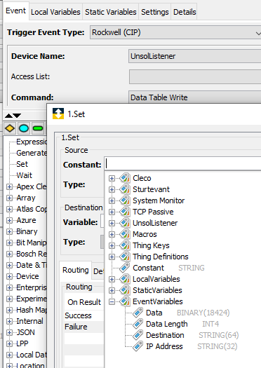
| Event Variables | Data Type | Description |
|---|---|---|
| Data | Varies depending upon selection | The data sent by the PLC. The data type can be either 1, 2, 4 or 8 Byte, Integer data, or 4 byte floating point data, or String data. User Defined Types (UDTs) can be sent in the Data Table Write. The Data Type for a UDT is Binary. |
| Data Length | UINT4 | The length of the data portion of the message. The length divided by the size of one item, will indicate the number of elements sent in the message. For example if the data length is 100 and the user is sending 4 byte integers, the message contains 25 items. The size of one UDT can be determined by clicking on the UDT in the Rockwell Logix 5000 software. |
| Destination | String Length 64 bytes | The value that was entered in the Destination field of the Data Table Write message in the Rockwell MSG block that is sending the message. |
| IP Address | STRING length of 32 | The IP Address of the PLC that sent the message |
Output Variables
| Event Variable | Data type | Description |
|---|---|---|
| Result Status | UINT1 | Return code to send back to the PLC. By default a value of 0 will be returned to the PLC. |