To define a trigger that executes when a Rockwell unsolicited message is sent, follow the steps below. For complete information on defining projects and triggers, see Defining a trigger
Every trigger identifies the trigger event type, which identifies when the trigger will be executed.
The PLC Logic Events category will list the available event types, based on the drivers that are installed on the node. The Rockwell driver supports the receipt of two types of unsolicited messages from Rockwell PLCs:
- The Rockwell (CIP) event type will support the receipt of unsolicited messages from Logix PLCs
- The Rockwell (PLC5/SLC) event type
will support the receipt of PLC-5 Typed Write or PLC-2
Unprotected Write messages from PLC-5 and SLC 500
PLC’s.

Unsolicited Logix Listener trigger - Rockwell (CIP)
To define a trigger that executes when a Rockwell Logix
unsolicited message is received, select the
Rockwell (CIP) trigger event type. The
event panel will change to display the parameters that the
trigger needs to process an unsolicited message. Each
unsolicited message type has parameters that are unique to
that type of message. The default unsolicited message is
the Set Single Attribute message, which is shown
below.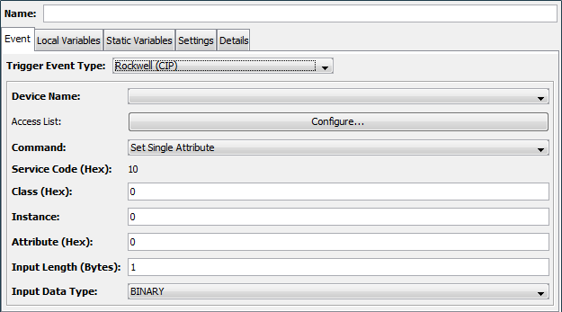
Unsolicited Logix Listener trigger parameters
The following parameters will be displayed on the trigger definition panel for every type of Rockwell (CIP) unsolicited message.
| Parameter | Description |
|---|---|
| Name | Enter a name for the trigger |
| Trigger Event Type | Under the PLC Logic Events category, select Rockwell (CIP). |
| Device Name | Select the name of the device that will send the unsolicited message. The devices in this list will be limited to those that are of the Unsolicited Logix Listener type when the Rockwell (CIP) trigger event type is selected. |
| Access List | The access list allows you to specify an IP filter associated with this trigger. This CIP Listener may receive messages from multiple IP addresses. The IP addresses defined in the access list can be used to limit which IP addresses will actually be allowed to execute this trigger. |
| Command | Select one of the following
Unsolicited Logix commands:
The driver can also process Write Tag Fragmented Message commands sent from the Logix PLC. The Logix PLC will send a message with this command code when a Data Table Write message has a payload that will not fit into a single packet. Additional parameters that define the payload associated with the unsolicited message will be displayed, depending upon which command is selected. |
| Max in Progress | On the Settings tab, enter the maximum number of instances of the trigger that can execute concurrently. |
| Max Exec Time (ms) | On the Settings tab, enter the maximum execution time for the trigger. If this time is exceeded, a warning message is written to the Exceptions log (even if Reporting is off). |
| Actions | Add the trigger actions required to implement the response desired for this Rockwell PLC unsolicited message. |
Unsolicited PLC-5 / SLC 500 Listener trigger
To define a trigger that executes when a Rockwell
PLC-5/SLC 500 unsolicited message is sent, select the
Rockwell (PLC5/SLC) trigger event type and
then set the trigger parameters as follows:
Unsolicited PLC-5/SLC 500 Listener trigger definition parameters
| Parameter | Description |
|---|---|
| Name | Enter a name for the trigger |
| Trigger Event Type | Under the PLC Logic Events category, select Rockwell (PLC5/SLC). |
| Device Name | Select the name of the device that will send the unsolicited message. The devices in this list will be limited to those that are of the Unsolicited PLC-5/SLC 500 Listener type when the Rockwell (PLC5/SLC) trigger event type is selected. |
| Access List | The access list allows you to specify an IP filter associated with this trigger. This PLC 5/SLC Listener may receive messages from multiple IP addresses. The IP Addresses defined in the access list can be used to limit which IP Addresses will actually be allowed to execute this trigger. |
| Command | Select either the PLC5 Typed Write or the PLC2 Unprotected Write option. |
| Data Table Address | Enter the same value as you defined in RSLogix software when creating the unsolicited event. For PLC5 Typed Write this is a string value, while the PLC2 Unprotected Write has an octal value that is in the range of 0 to 37777. |
| Message Length | The total length of the message. The total number of data elements was supplied in the RSLogix software. For example in the section titled Defining a Rockwell PLC5 Write unsolicited message using RSLogix 500, a message was defined containing a payload of 32 integers. To receive this message a value of 64 (32 x 2 bytes) would be entered in the Message Length parameter. |
| Data Type | Select the data type that matches the data in the message. |
| String Length | Displayed only when the String value in the Data Type field has been selected. Identifies the length of each String in the unsolicited message. |
| Max in Progress | On the Settings tab, enter the maximum number of instances of the trigger that can execute concurrently. |
| Max Exec Time (ms) | On the Settings tab, enter the maximum execution time for the trigger. If this time is exceeded, a warning message is written to the Exceptions log (even if Reporting is off). |
| Actions | Add the trigger actions required to implement the response desired for this Rockwell PLC unsolicited message. |
The Data Table Address parameter is used by the Rockwell driver as a value to compare against a received PLC5 Typed Write or a PLC2 Unprotected Write unsolicited message. A trigger that matches this parameter will be executed. The message will be dropped if there is no match.
Upon execution, the data sent by the unsolicited message will be available to the actions defined in a trigger as an event variable. An example of this would be using the Event.Variable.Data variable within the Source parameter of a Set action.
When the trigger ends its status and the data set in the “Event.Variable.Data” will be sent back to the PLC. The MSG instruction “DN” or “ER” bit will be set. The “DN” bit will be set if the trigger completes successfully. Triggers that complete in an error state will return an error code to the Logix PLC’s ladder logic. The MSG instruction could complete with errors and this is signaled by the ER bit set.