The Rockwell driver supports the reading and writing of an entire User Defined Type (UDT) tag from within trigger actions. Previously, each member of the UDT would have to be read or written separately, which required multiple trigger actions to process an entire UDT tag. The driver now supports processing the data for an entire UDT tag as a BINARY data type. The use of this is best seen through the following example.
Reading a UDT Tag
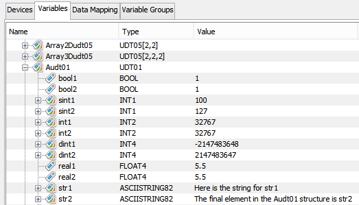
A tag has been defined on a Rockwell ControlLogix PLC named Audt01. It is an instance of a UDT named UDT01. UDT01 contains a mix of Boolean tags, Integer tags, and String tags as shown in the following image.
The Audt01 variable can now be read, in its entirety using either the Demand Read trigger action or the Set trigger action. In this example the Demand Read trigger action is used.
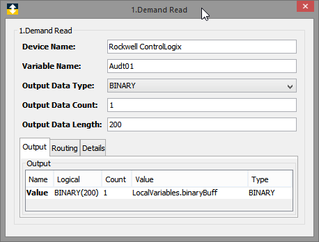
The data will be read from the Audt01 UDT into a binary buffer variable. The length of the buffer must be greater than or equal to the size of the UDT being read. In this example the size of the UDT01 UDT is 200 bytes. The size of the UDT can be determined in a couple of ways, the first of which is by using the Rockwell RSLogix 5000 software. Using the Rockwell RSLogix 5000 software, select the UDT in the User-Defined category of the Data Types menu on the Controller Organizer. The UDT size will be displayed in the overview window. This information is also available to users who don't have access to the RSLogix 5000 software by enabling the Create UDT Binary Description Files option on the Workbench's Device Definition panel for Rockwell ControlLogix and CompactLogix device types.
UDT Binary Description Files
There is a new field available when defining Rockwell ControlLogix and CompactLogix devices that will create UDT binary description files when the device is started. These JSON formatted files describe the binary payload associated with a UDT tag. An entry is made for each member in the UDT, describing its data type, the member's data offset in the payload, and any special handling needed to process the member's data. These files will be created when the device is started and the Create UDT Binary Description Files setting is enabled. The files will be stored in the node's Staging Browser area, under a directory named rockwell/json. Subdirectories bearing the name of the device will be created under the rockwell/json directory and will hold the UDT binary description files associated with the UDTs defined on the Rockwell PLC.
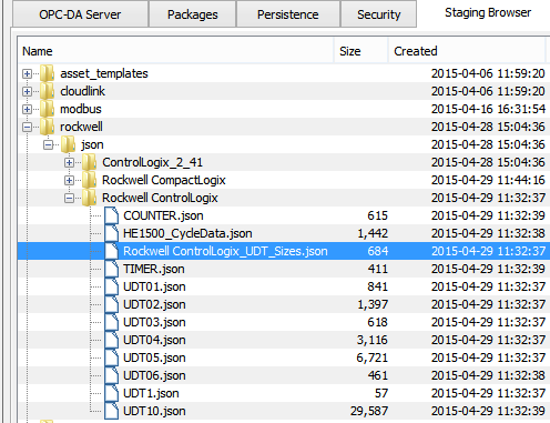
The Staging Browser image shown above better explains the directory structure and naming convention used by the UDT binary description files. The rockwell/json directory is shown, with subdirectories for each Rockwell ControlLogix and CompactLogix device. Individual JSON files are created for each UDT defined on the Rockwell PLC. There is also one special JSON file created for each device, as shown by the JSON file highlighted in the image. In this image the file named Rockwell_ControlLogix_UDT_Sizes.json was created and has an entry for each UDT defined on the device. The UDT entries show the size of each UDT defined on the Rockwell PLC. This information is provided to users who don't have access to the RSLogix 5000 software to determine this information. The size of the UDT is needed when reading a UDT tag, as stated in the previous section.
Converting UDT Binary Data to a Readable Format
The Decode Binary Buffer can be used to translate the UDT data from its binary format into a readable format. This translation can be directly to a device variable on another vendor's PLC, such as Mitsubishi or Siemens. It can also be translated to a local trigger variable for use later in the trigger, for example to a local variable that will be the data source for a data base insert.
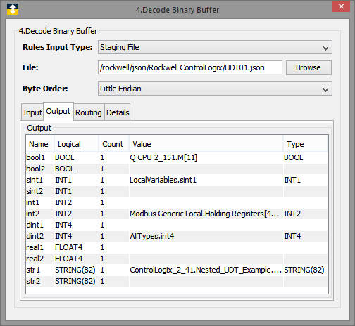
The image above shows examples of how the Decode Binary Buffer action can be used to translate the UDT data in its binary format into readable formats. In this example the UDT01.json file, which was created when the Rockwell ControlLogix device was started, is used to define the Output variables that can be referenced in this action. Each of the Output variables corresponds to a member in the UDT. In this example the value of the bool1 member will be written to a Mitsubishi Q PLC. The value of the sint1 member is written to a trigger local variable named sint1, while other variables are written to a Modbus device, a Global variable device, and a different ControlLogix device. Once the UDT data has been read from the ControlLogix device into a binary buffer, the Decode Binary Buffer action provides a great deal of flexibility in where the data will be moved and how it will be used.
Writing a UDT Tag
As outlined above, the steps to read an entire UDT are to first use the Demand Read or Set actions to get the data from the PLC into a binary buffer. Once in a binary buffer the data is translated using the Decode Binary Buffer action. The steps to write an entire UDT tag are similar, but different. First the readable data is translated into a binary buffer using the Encode Binary Buffer. The binary buffer is then written to the UDT tag using either the Demand Write or the Set action.
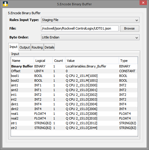
Like the Decode Binary Buffer action, the Encode Binary Buffer action makes use of the UDT Binary Description Files that were created when the ControlLogix or CompactLogix was started. The information in the UDT Binary Description File is used to create the Input variables needed by the Encode Binary Buffer action. The Input variables correspond to each member in the UDT. The example above shows how data can be mapped from a Mitsubishi Q PLC to UDT member locations in a binary buffer. The binary buffer will be populated with the values from the Mitsubishi Q PLC, once this action executes. The binary buffer will then be ready to be written to a UDT tag defined on either a ControlLogix or CompactLogix PLC using either a Demand Write trigger action or a Set trigger action.