The Workbench provides the view into a node's installation, configuration and resource definition. The Workbench also provides access and control over those resources.
A device is a resource that can represent a physical device, such as a programmable logic controller (PLC), an RF tag reader or a sensor. A device can also be defined in one node to represent a device that is defined and supported in another node. This allows your application solution to have access to devices and their data independent of their location or connectivity details.
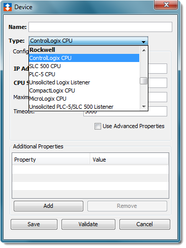
The following devices can be defined with the Rockwell driver:
- ControlLogix CPU
- SLC 500 CPU
- PLC-5 CPU
- Unsolicited Logix Listener
- CompactLogix CPU
- MicroLogix CPU
- Unsolicited PLC-5/SLC 500 Listener
- Micro800 CPU
The Unsolicited Logix Listener and the Unsolicited PLC-5/SLC 500 Listener are unique device types in that they do not represent a physical Rockwell PLC. These two “Listener” devices when started activate a process on the node that will listen for unsolicited messages sent from Rockwell PLCs. The Rockwell PLCs will be configured to route the unsolicited messages to a Listener device running on the node.
- The Logix Listener is able to receive
- Set Single Attribute - used when the PLC wants to send data to the node
- Get Single Attribute - used when the PLC wants to retrieve data from the node
- Data Table Write - typically this message type is used to transfer information from one Logix controller to another. A node can be substituted as the receiver of the Data Table Write request.
- Custom - used when the PLC wants to send data to the node and also expects data back from the node all within the execution of the MSG instruction.
- The PLC-5/SLC 500 Listener is able to receive
- PLC5 Typed Write messages
- PLC2 Unprotected Write messages.
To define a device that represents a Rockwell ControlLogix CPU device, follow these steps:
- From the Workbench left pane, expand the node where
you want to define the device.
- Select the Devices icon.
The Devices window appears as the right pane.
The Devices window provides a table format that lists the previously defined devices. - To define a new device, select New
at the bottom of the pane.
The Device window appears. The available device types are determined by the device support that is installed in this node. - Use the Type down-arrow, to select
ControlLogix CPU under the
Rockwell group.
- The Device window changes to accommodate the
selected device type.
-
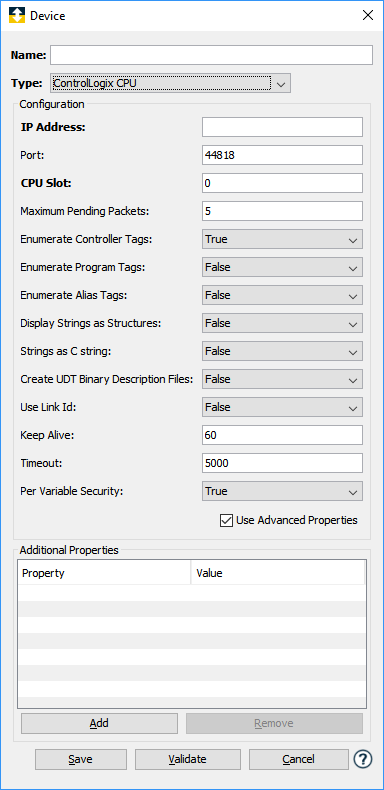
To define a device that represents a ControlLogix CPU, set this new device’s parameters as follows:
Parameter Description Name Enter a name for the Rockwell ControlLogix CPU device. Type Select ControlLogix CPU. IP Address Enter the IP Address of the device. Port Enter the port number used by the device. The default is 44818. CPU Slot Enter the slot in the rack for this CPU device. The first slot is always 0, and is counted from left to right. Maximum Pending Packets Enter the maximum number of pending (outstanding) packets for the device. This is a tuning parameter. Better performance can be achieved by increasing this number, however, if too many pending messages build up in the CPU, then it will start ignoring requests and you could receive timeouts in the driver. Enumerate Controller Tags Select True (the default) to query the ControlLogix device for the list of Controller tags (variables). Select False to omit Controller tags. Enumerate Program Tags Select True to query the ControlLogix device for the list of Program tags (variables). Select False (the default) to omit Program tags. Enumeration Option An option to control which objects are enumerated. The default value is All.
-
All - enumerates all Program tags.
-
Allowlist - enumerates the tags for the Programs defined by the Enumeration List parameter.
-
Denylist - enumerates the tags for all Programs except those identified by the Enumeration List parameter.
Enumeration List A comma-separated list of Program level tags to either enumerate or ignore. Only shown if the Enumeration Option parameter is Allowlist or Denylist.
-
A comma ',' is the separator between multiple Program names.
-
An asterisk wild card character '*' is supported for as the last portion of a Program name.
-
Example: Program:AProgramName, Program:Many*
Note: The wild card character is not allowed as the only value in the Enumeration List field.
Enumerate Alias Tags Select True to query the ControlLogix device for the list of Alias tags (variables). Select False (the default) to omit Alias tags. Display Strings as Structures Select:
True - In the Variables window, strings will be displayed with a structure containing a Length and individual Byte fields.
False - The default. In the Variables window, strings will be displayed as a single field.Strings as C string Select:
True - To have the Rockwell driver parse Rockwell strings and modify, if necessary, the string size based on the occurrence of a Null (0x00) character.
False - The default. To use the string size as specified in the Rockwell tagCreate UDT Binary Description Files This parameter is used to generate files that describe the layout of the binary data associated every User Defined Type (UDT) defined on the ControlLogix PLC. These files can then be used in conjunction with the Decode Binary Buffer action to translate binary data read from a UDT into variables. Likewise the Encode Binary Buffer action can be used to translate variable data into a binary format that can then be written to a UDT. True - Create the binary description files when the device is started.
False - The default. The binary description files will not be created when the device is started.Use Link ID This parameter affects the method by which the Rockwell driver requests variable information from a ControlLogix CPU. Utilizing a tag's Link ID will result in a slight improvement in performance when reading and writing tags, at the expense of a slower device start time. Select:
True - Variable read and write requests are made to the ControlLogix CPU using the tag's internal address.
False - The default. Variable read and write requests are made to the ControlLogix CPU using the name of the tag.Keep Alive Enter the number of seconds to wait before sending a heart beat message. Timeout Enter the timeout value to use when communicating with this device. This is entered in milliseconds. Per Variable Security Select False to disable the allocation of additional memory to track User to Variable access for all Variables in this Device. Select True to enable this feature if required. For more information, see Setting up Read Write per device variable.
The Rockwell Driver accepts an Additional Properties value for the ControlLogix device type that is used for the Read and Write timeout value when communicating with the device. In the Device window, Additional Properties section, select Add to display the New Item popup. Enter “message_ttl” (without the quotes) for the Property parameter and a timeout value in the Value parameter between 1 and 31. The units are seconds. If a value outside of this range is used, the default of 10 is used.
The parameters for enumerating Controller tags, Program tags and Alias tags allow you to determine which variables to enumerate. Omitting these variables from enumeration will reduce the amount of memory that is allocated when the device is Started. If variables are not enumerated when the device is Started, then those variables are not available for Read and Write access. -
- Select Validate to have the
parameters validated and to connect to the Rockwell
PLC. If there is a problem connecting to the Rockwell
PLC, an error code will be displayed.
- Select Save to save the device
definition. The device will appear in the Devices
window list of devices.
- You can now control the device (Start, Stop), access the device’s variables by using the Variables window, and build solutions that use the device’s resources.
Defining a Rockwell SLC 500 CPU or PLC-5 CPU device - Ethernet
To define a device that represents a Rockwell SLC 500 CPU or PLC-5 device with an Ethernet connection, repeat steps 3 through 8, set this new device’s parameters as follows:
| Parameter | Description |
|---|---|
| Name | Enter a name for the Rockwell SLC 500 CPU or PLC-5 CPU device. |
| Type | Select SLC 500 CPU or PLC-5 CPU. |
| Connection Type | Select Ethernet for a device with a direct Ethernet connection. |
| IP Address | Enter the IP Address of the device. |
| Port | Enter the port number used by the device. The default is 2222. |
| Automatic Enumeration | Select True or False. If set to True, automatically query the device’s registers and sizes. |
| File Registers | Enter the File Registers and sizes that should be enumerated if Automatic Enumeration is set to False. The format is Register/Size. For example a value of N7/15,F8/10,ST14/256 will create three File Registers, 15 integers at File Register 7, 10 floating point values at File Register 8, and 256 Strings at File Register 14. Setting the Automatic Enumeration to false places the responsibility on the user to ensure the definitions they specify match the File Register definitions defined on the physical device. |
| DF1 DST | Destination node for the message. Used when the IP Address is a DIGI device. The DF1 DST value identifies the slave address of the SLC 500 CPU or PLC-5 CPU device attached to the DIGI. |
| DF1 SRC | Source node of the message. Used when the IP Address is a DIGI device. The DF1 SRC is a user defined value that identifies the node sending the message. |
| Maximum Pending Packets | This option is available when configuring a SLC 500 CPU device type. Enter the maximum number of pending (outstanding) packets for the device. This is a tuning parameter. Better performance can be achieved by increasing this number, however, if too many pending messages build up in the CPU, then it will start ignoring requests and you could receive timeouts in the driver. |
| Timeout | Enter the timeout value to use when communicating with this device. This is entered in milliseconds. |
| Per Variable Security | Select False to disable the allocation of additional memory to track User to Variable access for all Variables in this Device. Select True to enable this feature if required. For more information, see Setting up Read Write per device variable. |
| Keep Alive | Enter the number of seconds to wait before sending a heart beat message. |
The Rockwell Driver accepts an Additional
Properties value for the SLC 500 and PLC-5 device
type that is used as a message retry value when
communicating with the device. It is possible for messages
routed to these devices to result in a timeout error
condition. The chances of receiving this message increase
when the interface is to a DIGI device that brokers the
Rockwell driver's TCP requests to the PLC via a serial
connection, receives the response from the PLC through the
Serial connection, and issues its reply back to the
Rockwell driver via the TCP Ethernet connection. The
message retry value provides a means to resend the message
rather than experiencing a timeout error condition.
In the Device window, Additional Properties section, select Add to display the New Item popup. Enter “max_retries” (without the quotes) for the Property parameter and a value between 1 and 5 in the Value. If a value outside of this range is used, the default of 3 is used. The Rockwell driver will attempt to resend a message, for up to 5 times, when it receives a timeout error condition, when the max_retries value is specified.
Defining a Rockwell SLC 500 CPU or PLC-5 CPU device - RS232
To define a device that represents a Rockwell SLC 500 CPU or PLC-5 device with a serial connection, repeat steps 3 through 8, set this new device’s parameters as follows:
| Parameter | Description |
|---|---|
| Name | Enter a name for the Rockwell SLC 500 CPU or PLC-5 CPU device. |
| Type | Select SLC 500 CPU or PLC-5 CPU. |
| Connection Type | Select RS232 for a device connected through an Ethernet to Serial bridge. |
| Serial port | The port through which the RS-232 connection will be made. The list of communication ports displayed will be appropriately generated based upon the node's operating system. |
| Baud rate | The baud rate used for the serial connection |
| Parity | Select the parity used for the serial connection |
| Stop bits | Select the number of stop bits used for the serial connection |
| Error Checking | Select the error checking used for the serial connection |
| Automatic Enumeration | Select True or False. If set to True, automatically query the device’s registers and sizes. |
| File Registers | Enter the File Registers and sizes that should be enumerated if Automatic Enumeration is set to False. The format is Register/Size. For example a value of N7/15,F8/10,ST14/256 will create three File Registers, 15 integers at File Register 7, 10 floating point values at File Register 8, and 256 Strings at File Register 14. Setting the Automatic Enumeration to false places the responsibility on the user to ensure the definitions they specify match the File Register definitions defined on the physical device. |
| Timeout | Enter the timeout value to use when communicating with this device. This is entered in milliseconds. |
| Per Variable Security | Select False to disable the allocation of additional memory to track User to Variable access for all Variables in this Device. Select True to enable this feature if required. For more information, see Setting up Read Write per device variable. |
| Keep Alive | Enter the number of seconds to wait before sending a heart beat message. |
Defining a Rockwell Unsolicited Logix Listener device
To define a device that represents a Rockwell Unsolicited Logix Listener device, repeat steps 3 through 8, set this new device’s parameters as follows:
| Parameter | Description |
|---|---|
| Name | Enter a name for the Rockwell Unsolicited Logix Listener device. |
| Type | Select Unsolicited Logix Listener. |
| Access List | The access list defines what IP addresses are allowed to connect to this node to send unsolicited messages. This parameter must be defined for the listener to work properly. |
| Port | Enter the port number used by the device. The default is 44818 and should be used under all circumstances to ensure that messages sent from Rockwell Logix PLCs can be received. If the port must be changed to something other than 44818, the change must also be made in the program on the ControlLogix device. See the section titled Defining a Rockwell Logix unsolicited message using RSLogix 5000 for details on how to define a message on the ControlLogix device, including defining the communications path to the Rockwell Unsolicited Logix Listener node. |
| Max Connections | This is the maximum number of connections that the listener is allowed to service at the same time. Care should be taken to create a reasonable limit based on the number of PLCs. |
| Per Variable Security | Select False to disable the allocation of additional memory to track User to Variable access for all Variables in this Device. Select True to enable this feature if required. For more information, see Setting up Read Write per device variable. |
Defining a Rockwell CompactLogix CPU device
To define a device that represents a Rockwell CompactLogix CPU device, repeat steps 3 through 8, set this new device’s parameters as follows:
| Parameter | Description |
|---|---|
| Name | Enter a name for the Rockwell CompactLogix CPU device. |
| Type | Select CompactLogix CPU. |
| IP Address | Enter the IP Address of the device. |
| Port | Enter the port number used by the device. The default is 44818. |
| Maximum Pending Packets | Enter the maximum number of pending (outstanding) packets for the device. This is a tuning parameter. Better performance can be achieved by increasing this number, however, if too many pending messages build up in the CPU, then it will start ignoring requests and you could receive timeouts in the driver. |
| Enumerate Controller Tags | Select True (the default) to query the CompactLogix device for the list of Controller tags (variables). Select False to omit Controller tags. |
| Enumerate Program Tags | Select True to query the CompactLogix device for the list of Program tags (variables). Select False (the default) to omit Program tags. |
| Enumeration Option |
An option to control which objects are enumerated. The default value is All.
|
| Enumeration list |
A comma-separated list of Program level tags to either enumerate or ignore. Only shown if the Enumeration Option parameter is Allowlist or Denylist.
Note: The wild card character is not allowed as the only value in the Enumeration List field. |
| Enumerate Alias Tags | Select True to query the CompactLogix device for the list of Alias tags (variables). Select False (the default) to omit Alias tags. |
| Display Strings as Structures | Select: True - In the Variables window, strings will be displayed with a structure containing a Length and individual Byte fields. False - The default. In the Variables window, strings will be displayed as a single field. |
| Strings as C string | Select: True - To have the Rockwell driver parse Rockwell strings and modify, if necessary, the string size based on the occurrence of a Null (0x00) character. False - The default. To use the string size as specified in the Rockwell tag |
| Create UDT Binary Description Files | This parameter is used to generate
files that describe the layout of the
binary data associated every User
Defined Type (UDT) defined on the
ControlLogix PLC. These files can then
be used in conjunction with the Decode
Binary Buffer action to translate
binary data read from a UDT into
variables. Likewise the Encode Binary
Buffer action can be used to translate
variable data into a binary format that
can then be written to a UDT.
True - Create the binary description files when the device is started. False - The default. The binary description files will not be created when the device is started. |
| Use Link ID | This parameter affects the method by
which the Rockwell driver requests
variable information from a
CompactLogix CPU. Utilizing a tag's
Link ID will result in a slight
improvement in performance when reading
and writing tags, at the expense of a
slower device start time. True - Variable read and write requests are made to the CompactLogix CPU using the tag's internal address. False - The default. Variable read and write requests are made to the CompactlLogix CPU using the name of the tag. |
| Keep Alive | Enter the number of seconds to wait before sending a heart beat message. |
| Timeout | Enter the timeout value to use when communicating with this device. This is entered in milliseconds. |
| Per Variable Security | Select False to disable the allocation of additional memory to track User to Variable access for all Variables in this Device. Select True to enable this feature if required. For more information, see Setting up Read Write per device variable. |
The Rockwell Driver accepts an Additional
Properties value for the CompactLogix device type
that is used for the Read and Write timeout value when
communicating with the device. In the Device window,
Additional Properties section, select Add to display the
New Item popup. Enter “message_ttl” (without the quotes)
for the Property parameter and a timeout value in the Value
parameter between 1 and 31. The units are seconds. If a
value outside of this range is used, the default of 10 is
used.
The parameters for enumerating Controller tags, Program tags and Alias tags allow you to determine which variables to enumerate. Omitting these variables from enumeration will reduce the amount of memory that is allocated when the device is Started. If variables are not enumerated when the device is Started, then those variables are not available for Read and Write access.
Defining a Rockwell MicroLogix CPU device - Ethernet
To define a device that represents a Rockwell MicroLogix CPU device with an Ethernet connection, repeat steps 3 through 8, set this new device’s parameters as follows:
| Parameter | Description |
|---|---|
| Name | Enter a name for the Rockwell MicroLogix CPU device. |
| Type | Select MicroLogix CPU. |
| Connection Type | Select Ethernet for a MicroLogix with a direct Ethernet connection. |
| IP Address | Enter the IP Address of the device. |
| Port | Enter the port number used by the device. The default is 44818. |
| Automatic Enumeration | Select True or False. If set to True, automatically query the device’s registers and sizes. |
| File Registers | Enter the File Registers and sizes that should be enumerated if Automatic Enumeration is set to False. The format is Register/Size. For example a value of N7/15,F8/10,ST14/256 will create three File Registers, 15 integers at File Register 7, 10 floating point values at File Register 8, and 256 Strings at File Register 14. Setting the Automatic Enumeration to false places the responsibility on the user to ensure the definitions they specify match the File Register definitions defined on the physical device. |
| Maximum Pending Packets | Enter the maximum number of pending (outstanding) packets for the device. This is a tuning parameter. Better performance can be achieved by increasing this number, however, if too many pending messages build up in the CPU, then it will start ignoring requests and you could receive timeouts in the driver. |
| Timeout | Enter the timeout value to use when communicating with this device. This is entered in milliseconds. |
| Per Variable Security | Select False to disable the allocation of additional memory to track User to Variable access for all Variables in this Device. Select True to enable this feature if required. For more information, see Setting up Read Write per device variable. |
| Keep Alive | Enter the number of seconds to wait before sending a heart beat message. |
Defining a Rockwell MicroLogix CPU device – Ethernet (DIGI)
To define a device that represents a Rockwell MicroLogix CPU device with an Ethernet to serial bridge connection, repeat steps 3 through 8, set this new device’s parameters as follows:
| Parameter | Description |
|---|---|
| Name | Enter a name for the Rockwell MicroLogix CPU device. |
| Type | Select MicroLogix CPU. |
| Connection Type | Select Ethernet (DIGI) for a MicroLogix connected through an Ethernet to Serial bridge. |
| IP Address | Enter the IP Address of the device. |
| Port | Enter the port number used by the device. The default is 44818. |
| Automatic Enumeration | Select True or False. If set to True, automatically query the device’s registers and sizes. |
| File Registers | Enter the File Registers and sizes that should be enumerated if Automatic Enumeration is set to False. The format is Register/Size. For example a value of N7/15,F8/10,ST14/256 will create three File Registers, 15 integers at File Register 7, 10 floating point values at File Register 8, and 256 Strings at File Register 14. Setting the Automatic Enumeration to false places the responsibility on the user to ensure the definitions they specify match the File Register definitions defined on the physical device. |
| DF1 DST | Destination node for the message. Used when the IP Address is a DIGI device. The DF1 DST value identifies the slave address of the SLC 500 CPU or PLC-5 CPU device attached to the DIGI. |
| DF1 SRC | Source node of the message. Used when the IP Address is a DIGI device. The DF1 SRC is a user defined value that identifies the node sending the message. |
| Timeout | Enter the timeout value to use when communicating with this device. This is entered in milliseconds. |
| Per Variable Security | Select False to disable the allocation of additional memory to track User to Variable access for all Variables in this Device. Select True to enable this feature if required. For more information, see Setting up Read Write per device variable. |
| Keep Alive | Enter the number of seconds to wait before sending a heart beat message. |
Defining a Rockwell MicroLogix CPU device - RS232
To define a device that represents a Rockwell MicroLogix CPU device with an RS232 connection, repeat steps 3 through 8, set this new device’s parameters as follows:
| Parameter | Description |
|---|---|
| Name | Enter a name for the Rockwell MicroLogix CPU device. |
| Type | Select MicroLogix CPU. |
| Connection Type | Select RS232 for a MicroLogix with a serial connection. |
| Serial port | The port through which the RS-232 connection will be made. The list of communication ports displayed will be appropriately generated based upon the node's operating system. |
| Baud rate | The baud rate used for the serial connection |
| Parity | Select the parity used for the serial connection |
| Stop bits | Select the number of stop bits used for the serial connection |
| Error Checking | Select the error checking used for the serial connection |
| Automatic Enumeration | Select True or False. If set to True, automatically query the device’s registers and sizes. |
| File Registers | Enter the File Registers and sizes that should be enumerated if Automatic Enumeration is set to False. The format is Register/Size. For example a value of N7/15,F8/10,ST14/256 will create three File Registers, 15 integers at File Register 7, 10 floating point values at File Register 8, and 256 Strings at File Register 14. Setting the Automatic Enumeration to false places the responsibility on the user to ensure the definitions they specify match the File Register definitions defined on the physical device. |
| Timeout | Enter the timeout value to use when communicating with this device. This is entered in milliseconds. |
| Per Variable Security | Select False to disable the allocation of additional memory to track User to Variable access for all Variables in this Device. Select True to enable this feature if required. For more information, see Setting up Read Write per device variable. |
| Keep Alive | Enter the number of seconds to wait before sending a heart beat message. |
Defining a Rockwell Unsolicited PLC-5/SLC 500 Listener device
To define a device that represents a Rockwell Unsolicited PLC-5/SLC 500 Listener device, repeat steps 3 through 8, set this new device’s parameters as follows:
| Parameter | Description |
|---|---|
| Name | Enter a name for the Rockwell Unsolicited PLC-5/SLC 500 Listener device. |
| Type | Unsolicited PLC-5/SLC 500 Listener. |
| Access List | The access list defines what IP addresses are allowed to connect to this node to send unsolicited messages. This parameter must be defined for the listener to work properly. |
| Port | Enter the port number used by the device. The default is 2222 and should be used under all circumstances to ensure that messages sent from all Rockwell PLC-5 and SLC 500 PLCs can be received. |
| Max Connections | This is the maximum number of connections that the listener is allowed to service at the same time. Care should be taken to create a reasonable limit based on the number of PLCs. |
| Per Variable Security | Select False to disable the allocation of additional memory to track User to Variable access for all Variables in this Device. Select True to enable this feature if required. For more information, see Setting up Read Write per device variable. |
Defining a Rockwell Micro800 device - Ethernet
To define a device that represents a Rockwell Micro800 device, repeat steps 3 through 8, set this new device’s parameters as follows:
| Parameter | Description |
|---|---|
| Name | Enter a name for the Rockwell Micro800 device. |
| Type | Micro800 CPU |
| IP Address | Enter the IP Address of the device. |
| Port | Enter the port number used by the device. The default is 44818. |
| Maximum Pending Packets | Enter the maximum number of pending (outstanding) packets for the device. This is a tuning parameter. Better performance can be achieved by increasing this number, however, if too many pending messages build up in the CPU, then it will start ignoring requests and you could receive timeouts in the driver. |
| Keep Alive | Enter the number of seconds to wait before sending a heart beat message. |
| Timeout | Enter the timeout value to use when communicating with this device. This is entered in milliseconds. |
| Per Variable Security | Select False to disable the allocation of additional memory to track User to Variable access for all Variables in this Device. Select True to enable this feature if required. For more information, see Setting up Read Write per device variable. |