Siemens PLCs provide two ways in which a message can be sent to the Siemens Listener running on a node. The first method is using the TCON, TSEND, TDISCON control blocks within a function. This method involves creating a DB that contains the data structure from the UDT 65 "TCON_PAR". This data structure contains the parameters necessary for configuring the connection. The defined connection can be either a TCP native connection or a ISO on TCP (RFC 1006) connection. Refer to chapter 23.3 Assigning Parameters for Communications Connections with TCP native and ISO on TCP, in the S7-300/400 System and Standard Functions Volume 2/2 document for details on how setting the parameters for both connection types. Using this DB, a TCON function can be performed to connect to the S7 Listener. Once connected the message is sent using the TSEND function. The message will be sent through the CPU's connection to the Industrial Ethernet, when using the TSEND function
The second way to send a message to the Siemens Listener involves defining a node on the NetPro panel to receive the message. Once this node is created a TCP connection is defined in the NetPro panel that links the S7 PLC to this new new node. The final step is to define an AG_Send block to send the message to the new node, through the newly created connection. In this scenario the message will be sent to the new node using the CP's connection to the Industrial Ethernet.

The sections that follow provide examples from the Siemens Step 7 software, of control blocks that configure and send a message from the S7 PLC to the Siemens driver.
Defining a Connection
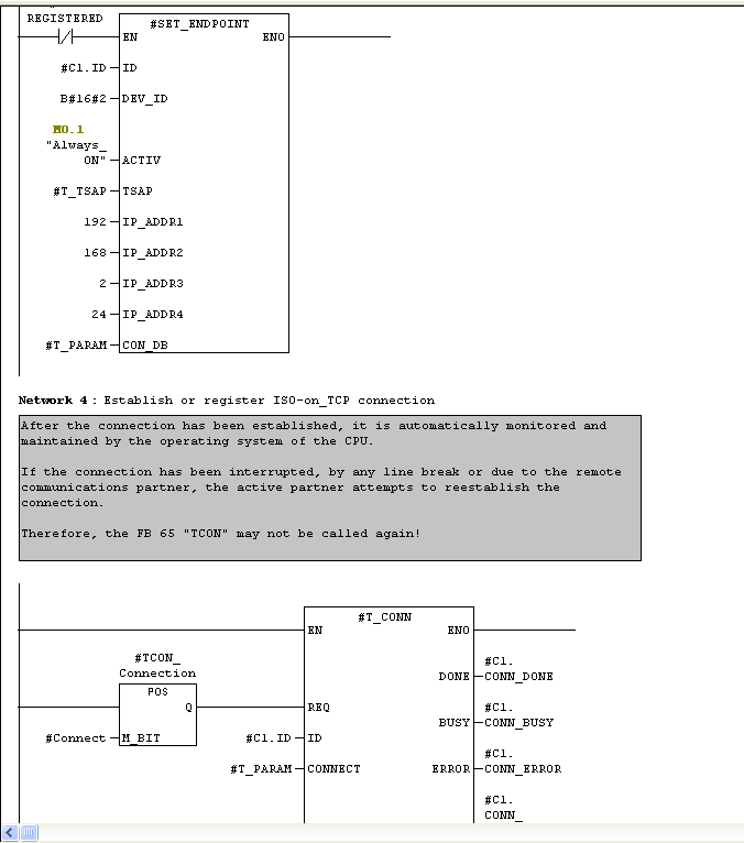
Whether sending a message using a TCP connection or an ISO on TCP connection, the first task to perform is to create a connection Endpoint. This image above shows how an Endpoint is defined and used by the function block to connect to the S7 Listener. The IP Address shown is the location of the node where the Listener is running. The T_CONN function uses the Endpoint to establish the connection to the node.
TCON, TSEND
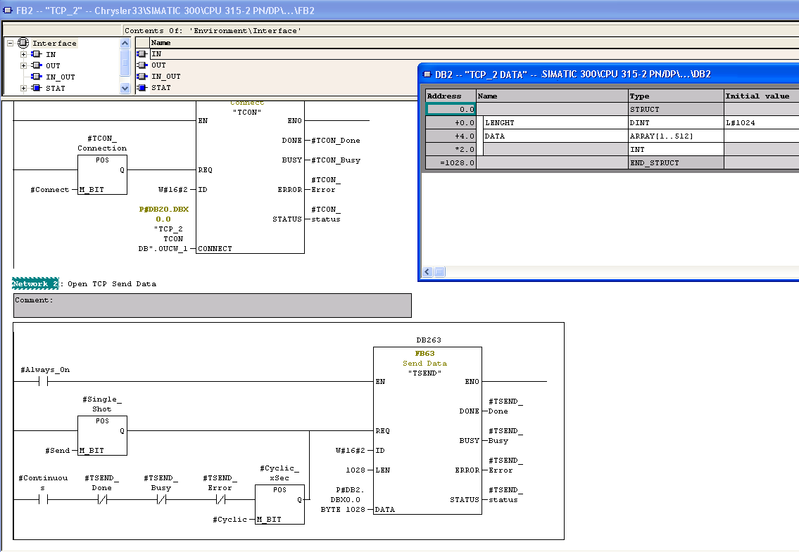 The image shown above
is an example of a Function Control Block (FCB) that
performs a TCON function, followed by the TSEND function.
The TSEND function will send the data to the S7 Listener.
Notice the DATA portion of the TSEND will send the DB2
block and will send 1028 bytes of data. An image of the DB2
block is shown in the image. Notice that the DB2 block
contains 1028 bytes. The 1028 bytes is broken up into two
sections, the first four bytes are the length of the buffer
and the data portion of the buffer is an array of 512 INTs.
An INT is two bytes, giving 1024 bytes of data. When using
the TSEND function to send a message to the S7 Listener,
the first four bytes of the buffer must indicate the number
of bytes being sent. In this example the buffer is
initialized with a value of 1024, but this value can be
changed to reflect the actual number of bytes being sent.
Of course if this value is changed, the LEN field of the
TSEND message must also be changed to reflect the number of
bytes to send.
The image shown above
is an example of a Function Control Block (FCB) that
performs a TCON function, followed by the TSEND function.
The TSEND function will send the data to the S7 Listener.
Notice the DATA portion of the TSEND will send the DB2
block and will send 1028 bytes of data. An image of the DB2
block is shown in the image. Notice that the DB2 block
contains 1028 bytes. The 1028 bytes is broken up into two
sections, the first four bytes are the length of the buffer
and the data portion of the buffer is an array of 512 INTs.
An INT is two bytes, giving 1024 bytes of data. When using
the TSEND function to send a message to the S7 Listener,
the first four bytes of the buffer must indicate the number
of bytes being sent. In this example the buffer is
initialized with a value of 1024, but this value can be
changed to reflect the actual number of bytes being sent.
Of course if this value is changed, the LEN field of the
TSEND message must also be changed to reflect the number of
bytes to send.
ISO on TCP (RFC1006)
The
S7
Listener can be defined to
receive messages that conform to the ISO on TCP standard.
The definition of the message and the function that sends
the message to the listener will change when using the ISO
on TCP communication protocol. 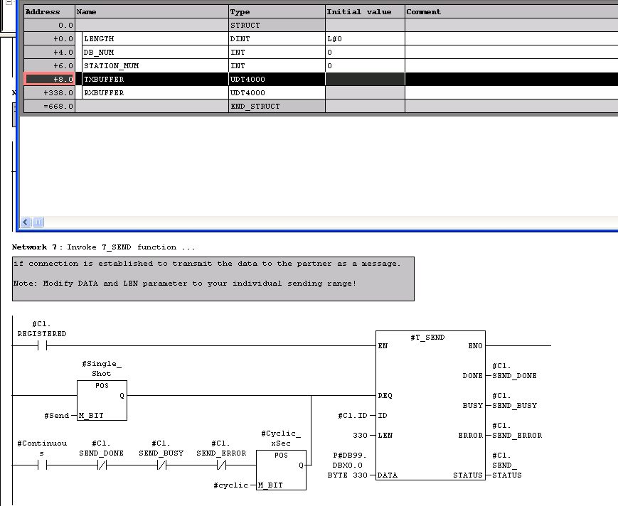
The T_SEND used for ISO on TCP messages is similar to the TSEND function, with one big difference. The T_SEND message does not include bytes that define the size of the message. The ISO on TCP protocol includes the message size in the header portion of the message, so the DATA portion of the message contains only the data. In the image above, the LEN field for the T_SEND function is 330 bytes and the DATA field is assigned to the DB99 block. The DB99 definition is also shown in the image and notice that the LEN value in the function matches the size of the DB99 TXBUFFER.
AG_Send
Define the node that will receive the TCP Send message
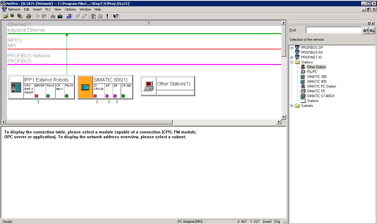
- From the Step 7 software, select the
Options->Configure Network menu selection. A view of
the the Siemens network map will be
displayed.
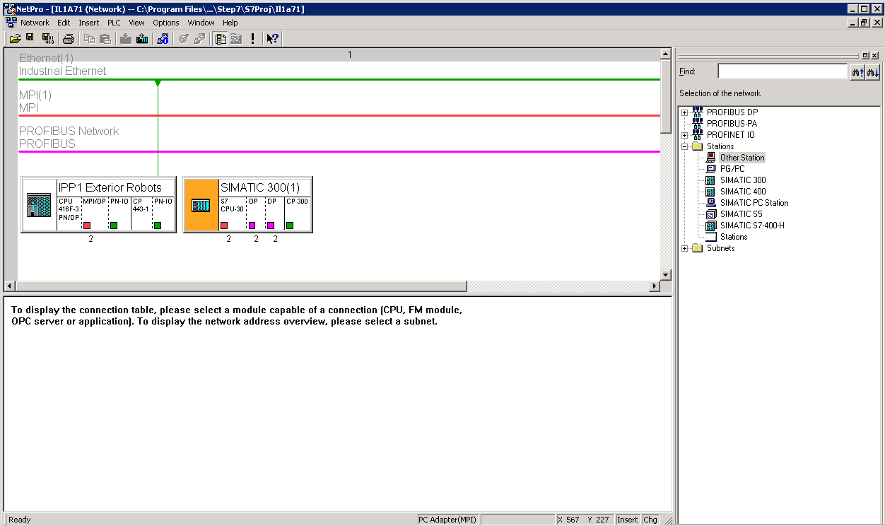
- Drag an Other Station object from
the Selection of the Network pane on the right side of
the display and drop it into the Network
diagram.
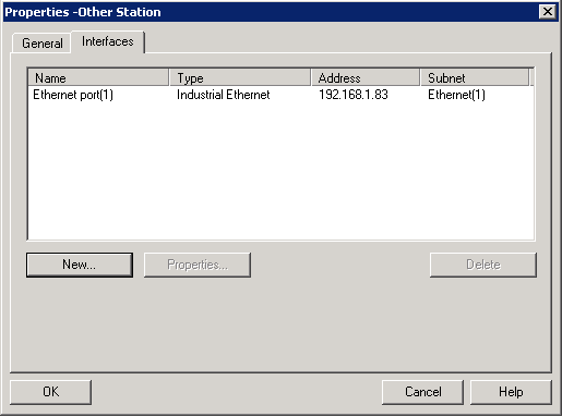
- Double Click the Other Station object added to the Network diagram to modify its parameters.
- On the General tab provide a unique name for the station. In this example the name S7 Listener has been entered into this field.
- Define the connection to this station on the Interfaces tab. Click the New button on the Interfaces tab to display the New Interface - Type Selection window.
- Select the Industrial Ethernet option and click the OK button. The Properties - Ethernet Interface tab will be displayed.
- Make sure the Set MAC Address check box is NOT selected.
- Modify the IP Address field to point to the node where the Siemens Listener is running.
- Select the Ethernet item in the Subnet window that will provide the communications link between the S7 PLC and the node.
- Press the OK button to return to the Properties -
Ethernet Interface tab.
- Press OK to save the settings for the Other
Station.
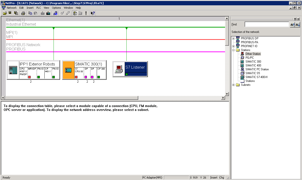
- Click the S7 Device shown in the diagram.
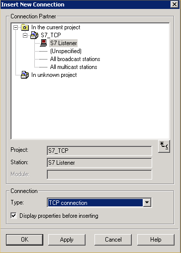
- Right click the CPU item of the PLC and select the Insert New Connection option.
- Select the Other Station item in the Insert New Connection window, S7 Listener in this example.
- Select TCP Connection for the Connection Type.
- Ensure the Display properties before inserting.
This will display a window that will provide
information that will be needed in the AG_Send
command.
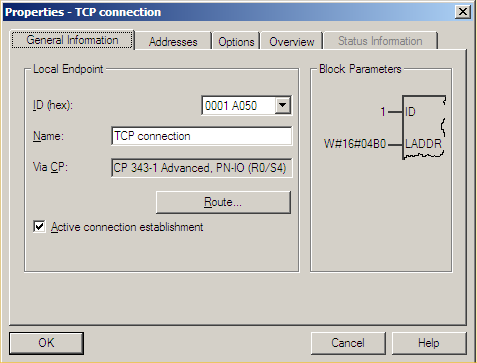
- Make note of the Block Parameters value for this
connection. This will be used in the AG_Send command.
Press OK to return to the Insert New Connection
panel.
- Press the OK key to save the connection.
AG_Send Function Block
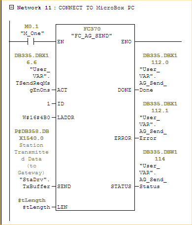
The above image is an example of the AG_SEND command. Notice how the Block parameters shown in the image above are entered in the ID and LADDR fields. This allows the AG_SEND message to be routed to the location of the S7 Listener.