The Siemens S7 Listener does not represent a physical Siemens PLC. Instead, this “Listener” device will listen for unsolicited TCP Send messages sent from Siemens PLCs. The ladder logic running on the Siemens PLCs must be configured to route the TCP Send message to the node.
Defining a Siemens S7 Listener device
To define a device that represents a Siemens S7 Listener
device, follow these steps:
- From the Workbench left pane, expand the node where
you want to define the device.
- Select the Devices icon.
The Devices window appears as the right pane.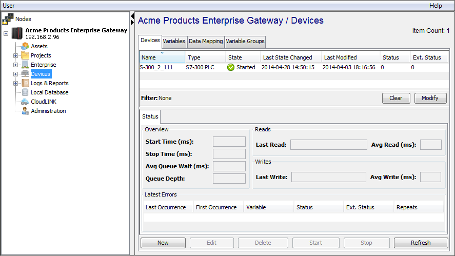
The Devices window provides a table format that lists the previously defined devices. - To define a new device, select New
at the bottom of the pane.
The Device window appears. The available device types are determined by the device support that is installed in this node. - Use the Type down-arrow, to select
Siemens S7 Listener under the
Siemens group.
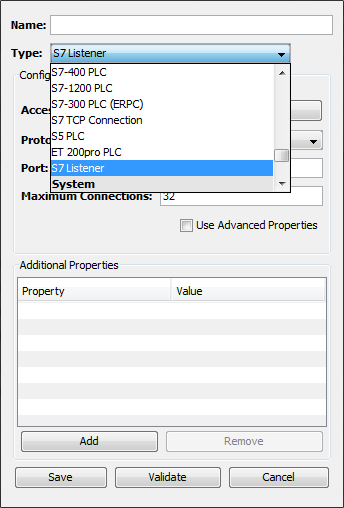
- The Device window changes to accommodate the
Siemens S7 Listener device type.
- To define a device that represents a Siemens S7
Listener, set this new device’s parameters as
follows:
Parameter
Description
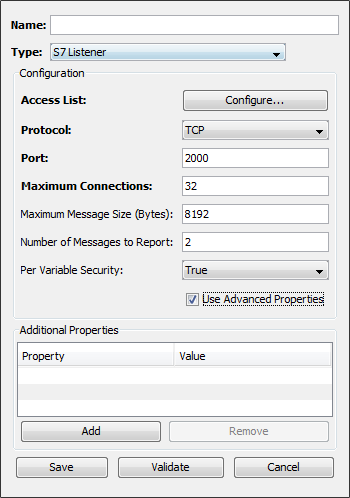
Name
Enter a name for the Siemens S7 Listener device.
Type
Select Siemens S7 Listener.
Access List
The access list defines what IP addresses are allowed to connect and send unsolicited messages to this node. This is done by either granting or denying access privileges to specific IP addresses or to entire IP subnets. Care must be taken when defining entries in the list to ensure that the listener works properly and receives messages from the intended PLCs.
Protocol
Select the communications protocol to use, either TCP or ISO on TCP
Port
Enter the port number used by the device. This field is shown only if the Protocol value is TCP. The default value is 2000. If the Protocol value is ISO on TCP the system will automatically use port 102.
Maximum Connections
This is the maximum number of PLC connections that the listener is allowed to service at the same time. Care should be taken to create a reasonable limit based on the number of PLCs that will be sending TCP Send messages to the node. The default value is 32.
Maximum Message Size
Enter the maximum size of the message that the listener will process. This value is the size of the message in bytes. The default value is 8192 bytes. Messages that exceed 65535 bytes will be refused by the listener.
Number of Messages to Report
Enter the number of messages the Listener should keep track of, for reporting purposes, on a per connection basis. These messages can be viewed on the Workbench Variables panel
Per Variable Security
Select False to disable the allocation of additional memory to track User to Variable access for all Variables in this Device. Select True to enable this feature if required. For more information, see Setting up Read Write per device variable.
- Select Validate to have the
parameters validated. If there is a problem, an error
code will be displayed.
- Select Save to save the device
definition. The device will appear in the Devices
window list of devices.
- You can now control the device
(Start, Stop), access
the device’s variables by using the
Variables window, and build solutions
that use the device’s resources.