The Workbench provides the view into a node's installation, configuration and resource definition. The Workbench also provides access and control over those resources.
A device is a resource that can represent a physical device, such as a programmable logic controller (PLC), an RF tag reader or a sensor. A device can also be defined in one node to represent a device that is defined and supported in another node. This allows your application solution to have access to devices and their data independent of their location or connectivity details.
The following devices can be defined with the Siemens S7 driver:
- Siemens S7-200
- Siemens S7-300
- Siemens S7-400
- Siemens S7-1200
- Siemens S7-1500
- Siemens LOGO!
- Siemens S5
To define a device that represents a Siemens S7-200 PLC device, follow these steps:
- From the Workbench left pane, expand the node where
you want to define the device.
- Click Devices.
The Devices window appears in the right pane.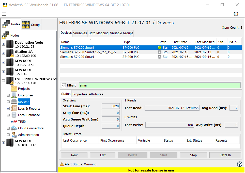
The Devices window provides a table format that lists the previously defined devices. - Click New to define a new device.
The Device window appears. The available device types are determined by the device support that is installed in this node. - Use the Type down-arrow, to select
S7-200 PLC under the
Siemens group.

The Device window changes to accommodate the selected device type. - To define a device that represents a S7-200 PLC,
set this new device’s parameters as follows: Siemens S7-200 PLC Required
Parameters. You will see additional settings, when you select the Advanced
Properties checkbox.
Parameter Description Name Enter a name for the Siemens S7-200 PLC device. Type Select S7-200 PLC. Connection Select the type of connection being made to the S7-200. There are three options, Direct, IBH Link S7++, and ACCON NetLink-Pro. The Direct option should be selected, unless the connection to the PLC is through either of the two third party devices, instead of through the CP. IP Address Enter the IP Address of the device. Rack Specify the rack location of the PLC. This option will appear if either the IBH Link S7++ or the ACCON NetLink-Pro Connection option is selected. CPU Slot Specify the location (slot number) of the PLC in the rack. This option will appear if either the IBH Link S7++ or the ACCON NetLink-Pro Connection option is selected. Advanced Properties Port Specify the TCP port on which to establish communication with the S7-200 PLC. PLC Model Select a Generic S7-200 or Smart S7-200 PLC. Note that the Siemens S7-200 Smart only allows 1 connection in its default configuration. PDU Size Specify the maximum size in bytes of a Protocol Data Unit for the S7-200 PLC. Timeout Specify the device timeout in milliseconds. I Register Size Specify the maximum size in bytes of the I Register Block on the S7-200 PLC. Q Register Size Specify the maximum size in bytes of the Q Register Block on the S7-200 PLC. M Register Size Specify the maximum size in bytes of the M Register Block on the S7-200 PLC. Max. Number of Pending Messages Enter the maximum number of pending (outstanding) messages for the device. This is a tuning parameter. Better performance can be achieved by setting this value to two, however, if too many pending messages build up in the PLC, then it will start ignoring requests and you could receive timeouts in the driver. Keep Alive1 A value, in seconds, in which the driver should send a message to the Siemens S7 PLC to ensure the communications link is still active. This message will only be sent if there has been no communications with the PLC for the amount of time specified in this field.
Enter a value of 0 to disable the Keep Alive messaging feature.Per Variable Security Select False to disable the allocation of additional memory to track User to Variable access for all Variables in this Device. Select True to enable this feature if required. For more information, see Setting up Read Write per device variable. - Select Validate to have the
parameters validated and to connect to the Siemens PLC.
If there is a problem connecting to the Siemens PLC, an
error code will be displayed.
- Select Save to save the device
definition. The device will appear in the Devices
window list of devices.
- You can now control the device (Start, Stop), access the device’s variables by using the Variables window, and build solutions that use the device’s resources.
To define a device that represents a Siemens S7-300 PLC
device, repeat steps 3 through 8 from the Siemens S7-200 PLC Device and set this new device’s
parameters as follows: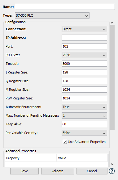
Siemens S7-300 PLC Required Parameters
| Parameter | Description |
|---|---|
| Name | Enter a name for the Siemens S7-300 PLC device. |
| Type | Select S7-300 PLC. |
| Connection | Select the type of connection being made to the S7-300. There are three options, Direct, IBH Link S7++, and ACCON NetLink-Pro. The Direct option should be selected, unless the connection to the PLC is through either of the two third party devices, instead of through the CP. |
| IP Address | Enter the IP Address of the device. |
| Rack | Specify the rack location of the PLC. This option will appear if either the IBH Link S7++ or the ACCON NetLink-Pro Connection option is selected. |
| CPU Slot | Specify the location (slot number) of the PLC in the rack. This option will appear if either the IBH Link S7++ or the ACCON NetLink-Pro Connection option is selected. |
Siemens S7-300 PLC Advanced Properties
(optional)
| Parameter | Description |
|---|---|
| Port | Specify the TCP port on which to establish communication with the S7-300 PLC. |
| PDU Size | Specify the maximum size in bytes of a Protocol Data Unit for the S7-300 PLC. |
| Timeout | Specify the device timeout in milliseconds |
| I Register Size | Specify the maximum size in bytes of the I Register Block on the S7-300 PLC. |
| Q Register Size | Specify the maximum size in bytes of the Q Register Block on the S7-300 PLC. |
| M Register Size | Specify the maximum size in bytes of the M Register Block on the S7-300 PLC |
| PIW Register Size | Specify the maximum size in bytes of the PIW Register Block on the S7-300 PLC |
| Automatic Enumeration | Specify True or False. If set to True, automatically query the device’s data blocks and sizes |
| Data Blocks | If Automatic Enumeration is set to False, a list of available data blocks in the format “DB1/50,DB10/100”, where DB1 is the data block name and 50 is the data block maximum size. |
| Max. Number of Pending Messages | Enter the maximum number of pending (outstanding) messages for the device. This is a tuning parameter. Better performance can be achieved by setting this value to two, however, if too many pending messages build up in the PLC, then it will start ignoring requests and you could receive timeouts in the driver. |
| Keep Alive1 | A value, in seconds, in which the
driver should send a message to the Siemens
S7 PLC to ensure the communications link is
still active. This message will only be
sent if there has been no communications
with the PLC for the amount of time
specified in this field. Enter a value of 0 to disable the Keep Alive messaging feature. |
| Per Variable Security | Select False to disable the allocation of additional memory to track User to Variable access for all Variables in this Device. Select True to enable this feature if required. For more information, see Setting up Read Write per device variable. |
To define a device that represents a Siemens S7-400 PLC
device, repeat steps 3 through 8 from the Siemens S7-200 PLC Device and set this new device’s
parameters as follows: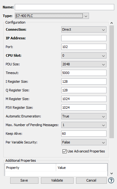
Siemens S7-400 PLC Required Parameters
| Parameter | Description |
|---|---|
| Name | Enter a name for the Siemens S7-400 PLC device. |
| Type | Select S7-400 PLC. |
| Connection | Select the type of connection being made to the S7-400. There are three options, Direct, IBH Link S7++, and ACCON NetLink-Pro. The Direct option should be selected, unless the connection to the PLC is through either of the two third party devices, instead of through the CP. |
| IP Address | Enter the IP Address of the device. |
| Rack | Specify the rack location of the PLC. This option will appear if either the IBH Link S7++ or the ACCON NetLink-Pro Connection option is selected. |
| CPU Slot | Specify the location (slot number) of the PLC in the rack. |
Siemens S7-400 PLC Advanced Properties
(optional)
| Parameter | Description |
|---|---|
| Port | Specify the TCP port on which to establish communication with the S7-400 PLC. |
| PDU Size | Specify the maximum size in bytes of a Protocol Data Unit for the S7-400 PLC. |
| Timeout | Specify the device timeout in milliseconds. |
| I Register Size | Specify the maximum size in bytes of the I Register Block on the S7-400 PLC. |
| Q Register Size | Specify the maximum size in bytes of the Q Register Block on the S7-400 PLC. |
| M Register Size | Specify the maximum size in bytes of the M Register Block on the S7-400 PLC. |
| PIW Register Size | Specify the maximum size in bytes of the PIW Register Block on the S7-400 PLC. |
| Automatic Enumeration | Specify True or False. If set to True, automatically query the device’s data blocks and sizes. |
| Data Blocks | If Automatic Enumeration is set to False, a list of available data blocks in the format “DB1/50,DB10/100”, where DB1 is the data block name and 50 is the data block maximum size. |
| Max. Number of Pending Messages | Enter the maximum number of pending (outstanding) messages for the device. This is a tuning parameter. Better performance can be achieved by setting this value to two, however, if too many pending messages build up in the PLC, then it will start ignoring requests and you could receive timeouts in the driver. |
| Keep Alive1 | A value, in seconds, in which the
driver should send a message to the Siemens
S7 PLC to ensure the communications link is
still active. This message will only be
sent if there has been no communications
with the PLC for the amount of time
specified in this field. Enter a value of 0 to disable the Keep Alive messaging feature. |
| Per Variable Security | Select False to disable the allocation of additional memory to track User to Variable access for all Variables in this Device. Select True to enable this feature if required. For more information, see Setting up Read Write per device variable. |
To define a device that represents a Siemens S7-1200 PLC
device, repeat steps 3 through 8 from the Siemens S7-200 PLC Device and set this new device’s
parameters as follows: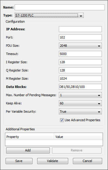
Siemens S7-1200 PLC Required
Parameters
| Parameter | Description |
|---|---|
| Name | Enter a name for the Siemens S7-1200 PLC device. |
| Type | Select S7-1200 PLC. |
| IP Address | Enter the IP Address of the device. |
| Data Blocks |
The options are Generic and TIA_Portal_DB_file:
Above, the listed examples are just figurative explanations. When entering the information onto deviceWISE Fields, make sure to enter the names that reflect your DB Files. DB Files which are in a List of Data Blocks property need to be placed in staging/siemens folder using the Staging Browser of deviceWISE Node before Device Start. Use TIA (Totally Integrated Automation) Portal PLC SW to generate the files. Click here to access their website. Click here to see the Siemens S7 DB Generation tutorial. See the table of Unsupported Siemens Data Types at the bottom of the page. |
Siemens S7-1200 PLC Advanced Properties
(optional)
| Parameter | Description |
|---|---|
| Port | Specify the TCP port on which to establish communication with the S7-1200 PLC. |
| PDU Size | Specify the maximum size in bytes of a Protocol Data Unit for the S7-1200 PLC. |
| Timeout | Specify the device timeout in milliseconds. |
| I Register Size | Specify the maximum size in bytes of the I Register Block on the S7-1200 PLC. |
| Q Register Size | Specify the maximum size in bytes of the Q Register Block on the S7-1200 PLC. |
| M Register Size | Specify the maximum size in bytes of the M Register Block on the S7-1200 PLC. |
| Max. Number of Pending Messages | Enter the maximum number of pending (outstanding) messages for the device. This is a tuning parameter. Better performance can be achieved by setting this value to two, however, if too many pending messages build up in the PLC, then it will start ignoring requests and you could receive timeouts in the driver. |
| Keep Alive1 | A value, in seconds, in which the
driver should send a message to the Siemens
S7 PLC to ensure the communications link is
still active. This message will only be
sent if there has been no communications
with the PLC for the amount of time
specified in this field. Enter a value of 0 to disable the Keep Alive messaging feature. |
| Per Variable Security | Select False to disable the allocation of additional memory to track User to Variable access for all Variables in this Device. Select True to enable this feature if required. For more information, see Setting up Read Write per device variable. |
To define a device that represents a Siemens S7-1500 PLC device, repeat steps 3 through 8 from the Siemens S7-200 PLC Device and set this new device’s parameters as follows:

Siemens S7-1500 PLC Required
Parameters
| Parameter | Description |
|---|---|
| Name | Enter a name for the Siemens S7-1500 PLC device. |
| Type | Select S7-1500 PLC. |
| IP Address | Enter the IP Address of the device. |
| Data Blocks |
The options are Generic and TIA_Portal_DB_file:
Above, the listed examples are just figurative explanations. When entering the information onto deviceWISE Fields, make sure to enter the names that reflect your DB Files. DB Files which are in a List of Data Blocks property need to be placed in staging/siemens folder using the Staging Browser of deviceWISE Node before Device Start. Use TIA (Totally Integrated Automation) Portal PLC SW to generate the files. Click here to access their website. Click here to see the Siemens S7 DB Generation tutorial. See the table of Unsupported Siemens Data Types at the bottom of the page. |
Siemens S7-1500 PLC Advanced Properties
(optional)
| Parameter | Description |
|---|---|
| Port | Specify the TCP port on which to establish communication with the S7-1500 PLC. |
| PDU Size | Specify the maximum size in bytes of a Protocol Data Unit for the S7-1500 PLC. |
| Timeout | Specify the device timeout in milliseconds. |
| I Register Size | Specify the maximum size in bytes of the I Register Block on the S7-1500 PLC. |
| Q Register Size | Specify the maximum size in bytes of the Q Register Block on the S7-1500 PLC. |
| M Register Size | Specify the maximum size in bytes of the M Register Block on the S7-1500 PLC. |
| Max. Number of Pending Messages | Enter the maximum number of pending (outstanding) messages for the device. This is a tuning parameter. Better performance can be achieved by setting this value to two, however, if too many pending messages build up in the PLC, then it will start ignoring requests and you could receive timeouts in the driver. |
| Keep Alive1 | A value, in seconds, in which the
driver should send a message to the Siemens
S7 PLC to ensure the communications link is
still active. This message will only be
sent if there has been no communications
with the PLC for the amount of time
specified in this field. Enter a value of 0 to disable the Keep Alive messaging feature. |
| Per Variable Security | Select False to disable the allocation of additional memory to track User to Variable access for all Variables in this Device. Select True to enable this feature if required. For more information, see Setting up Read Write per device variable. |
To define a device that represents a Siemens LOGO! PLC device, repeat steps 3 through 8 from the Siemens S7-200 PLC Device and set this new device’s parameters as follows:

Siemens LOGO! PLC Required
Parameters
| Parameter | Description |
|---|---|
| Name | Enter a name for the Siemens LOGO! PLC device. |
| Type | Select LOGO! PLC. |
| IP Address | Enter the IP Address of the LOGO! device. |
Siemens LOGO! PLC Advanced Properties (optional)
| Parameter | Description |
|---|---|
| Port | Specify the TCP port on which to establish communication with the LOGO! PLC. |
| PDU Size | Specify the maximum size in bytes of a Protocol Data Unit for the LOGO! PLC. |
| Timeout | Specify the device timeout in milliseconds. |
| TSAP | The TSAP of the deviceWISE node connecting to the LOGO!. The default value is 20 |
| Max. Number of Pending Messages | Enter the maximum number of pending (outstanding) messages for the device. This is a tuning parameter. Better performance can be achieved by setting this value to two, however, if too many pending messages build up in the PLC, then it will start ignoring requests and you could receive timeouts in the driver. |
| Keep Alive1 | A value, in seconds, in which the
driver should send a message to the Siemens
LOGO! PLC to ensure the communications link
is still active. This message will only be
sent if there has been no communications
with the PLC for the amount of time
specified in this field. Enter a value of 0 to disable the Keep Alive messaging feature. |
| Per Variable Security | Select False to disable the allocation of additional memory to track User to Variable access for all Variables in this Device. Select True to enable this feature if required. For more information, see Setting up Read Write per device variable. |
To define a device that represents a Siemens S5 PLC device, repeat steps 3 through 8 from the Siemens S7-200 PLC Device and set this new device’s parameters as follows:
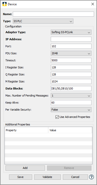
Siemens S5 PLC Required
Parameters
| Parameter | Description |
|---|---|
| Name | Enter a name for the Siemens S5 PLC device. |
| Type | Select S5 PLC. |
| Adapter Type | Select either Softing S5-PCLink or IBH Softec S5++. The ACCON S5-LAN IP is not listed but is supported. |
| IP Address | Enter the IP Address of the S5 device. |
Siemens S5 PLC Advanced Properties (optional)
| Parameter | Description |
|---|---|
| Port | Specify the TCP port on which to establish communication with the S5 PLC. |
| PDU Size | Specify the maximum size in bytes of a Protocol Data Unit for the S5 PLC. |
| Timeout | Specify the device timeout in milliseconds. |
| I Register Size | Specify the maximum size in bytes of the I Register Block on the S5 PLC. |
| Q Register Size | Specify the maximum size in bytes of the Q Register Block on the S5 PLC. |
| M Register Size | Specify the maximum size in bytes of the M Register Block on the S5 PLC. |
| Data Blocks | A list of available data blocks in the format “DB1/50,DB10/100”, where DB1 is the data block name and 50 is the data block maximum size. |
| Max. Number of Pending Messages | Enter the maximum number of pending (outstanding) messages for the device. This is a tuning parameter. Better performance can be achieved by setting this value to two, however, if too many pending messages build up in the PLC, then it will start ignoring requests and you could receive timeouts in the driver. |
| Keep Alive1 | A value, in seconds, in which the
driver should send a message to the Siemens S5 PLC to ensure the communications link
is still active. This message will only be
sent if there has been no communications
with the PLC for the amount of time
specified in this field. Enter a value of 0 to disable the Keep Alive messaging feature. |
| Per Variable Security | Select False to disable the allocation of additional memory to track User to Variable access for all Variables in this Device. Select True to enable this feature if required. For more information, see Setting up Read Write per device variable. |
1For the Siemens Listener to detect connection loss, whilst the connection is open the system needs to turn on the TCP/IP stack keepalive function. The Siemens listener is configured for the Keepalive process, addtionally the networking stack has to be configured. The KeepAlive mechanism does not disconnect idle TCP/IP connections. If configured to the remote stack the networking stack sends heartbeat signals automatically. In many operating system, the default keepalive inactivity time, when the stack will send a probe is large, typically two hours. In order to reduce this time for better and quicker cleanup, the stack has to be configured with a smaller time. The way this smaller time is setup is different for each operating system. For example, if deviceWISE is running on windows, the registry entry is reconfigured to a lesser value, for instance it is set to 1 minute instead of the default value of 2 hours. For windows, follow the process described here. For other operating systems it varies, check the operating system info for further details. For example, for some Linux systems, see here.
The following Siemens Data Types are not supported at this moment. If present, they will be ignored while Parsing the .db.
| Siemens Type | Size |
|---|---|
| AOM_IDENT | 32 |
| CONN_ANY | 16 |
| CONN_OUC | 16 |
| CONN_PRG | 16 |
| CRE | 64 |
| DB_ANY | 16 |
| DB_DYN | 16 |
| DB_WWW | 16 |
| DTL | 96 |
| Date | 16 |
| EVENT_ANY | 32 |
| EVENT_ATT | 32 |
| EVENT_HWINT | 32 |
| ErrorStruct | 224 |
| HW_ANY | 16 |
| HW_DEVICE | 16 |
| HW_DPSLAVE | 16 |
| HW_HSC | 16 |
| HW_IEPORT | 16 |
| HW_INTERFACE | 16 |
| HW_IO | 16 |
| HW_IOSYSTEM | 16 |
| HW_PTO | 16 |
| HW_PWM | 16 |
| HW_SUBMODULE | 16 |
| IEC_COUNTER | 48 |
| IEC_DCOUNTER | 96 |
| IEC_SCOUNTER | 32 |
| IEC_TIMER | 128 |
| IEC_UCOUNTER | 48 |
| IEC_UDCOUNTER | 96 |
| IEC_USCOUNTER | 32 |
| NREF | 64 |
| OB_ANY | 16 |
| OB_ATT | 16 |
| OB_CYCLIC | 16 |
| OB_DIAG | 16 |
| OB_HWINT | 16 |
| OB_PCYCLE | 16 |
| OB_STARTUP | 16 |
| OB_TIMEERROR | 16 |
| OB_TOD | 16 |
| PIP | 16 |
| PORT | 16 |
| RTM | 16 |
| Time | 32 |
| Time_Of_Day | 64 |