The following section provides an example of how a BUFSND message is defined on a Mitsubishi Q CPU, for routing to the Mitsubishi Listener device.
To utilize the BUFSND Event Type with the Mitsubishi Listener device you must define a connection in the QJ71E71-100 Module and write a PLC program to utilize this connection.
The first step is to configure the QJ71E71-100 module. You will need to know the following information:
- Module address in PLC CPU Memory
- IP Address to configured for the Module
- MELSECNET Network Number and Station number
- IP Address of the node where the Mitsubishi Listener is running that will receive the BUFSND message
- Port number that the Mitsubishi Listener will be using
- The number of words of data the BUFSND event is configured to send
In this example the following settings will be used:
- QJ71E71-100 PLC CPU Memory: H00
- QJ71E71-100 IP Address: 192.168.3.4
- QJ71E71-100 MELSECNET Network: 1
- QJ71E71-100 MELSECNET Station No.: 1
- IP Address of the Mitsubishi Listener node 192.168.3.3
- Mitsubishi Listener Port Number: 1234
- BUFSND Event number of words: 8
Configuring the QJ71E71-100
- In GX Works2 navigate the Project tree to:
Project|Parameter| Network Parameter|Ethernet/CC IE /MELSECNET - And add an Ethernet Module

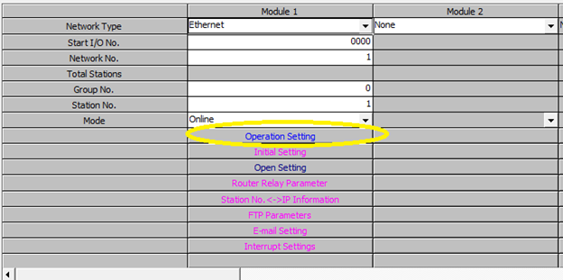
- Configure the Module by supplying values for the
following fields:
- Start I/O No.
- Network No.
- Group No.
- Station No.
- Mouse click the Operation
Setting field.
- This will display the Ethernet Operation Setting
dialog box.
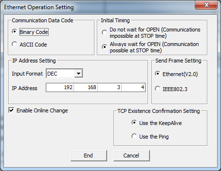
- Enter the IP Address for the QJ71E71-100 and click the End button to save the setting. The dialog box will disappear and the previous panel will be displayed.
- Mouse click on the Open Setting field.
- Define the setting that will define the
communication path to the Mitsubishi Listener.
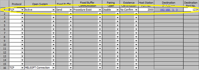
- Define values for the following fields.
- Protocol - TCP
- Open System - Active
- Fixed Buffer - Send
- Fixed Buffer Communication - Procedure Exist
- Pairing Open - Disable
- Existence Confirmation - No Confirm
- Host Station Port No. - The port that will be used by the Mitsubishi CPU to send the message.
- Destination IP Address: The IP address of the node where the Mitsubishi Listener device is running.
- Destination Port No. - The Port that the Mitsubishi Listener has opened to receive messages. The section titled Using the Workbench to Define a Mitsubishi Listener device contains instructions on how to define the Port and other parameters for the Mitsubishi Listener
- Click the End button to save the connection information.
Writing a program on the Mitsubishi CPU to send the BUFSND message
It is not the intention of this documentation to teach PLC programming for the Mitsubishi CPUs. Instead an example program will be presented that shows how the ladder logic can be written to send a BUFSND message. In this example two PLC programs have been written.
INITIAL.PRG
This program will load defaults to use for sending data. This program has been placed in the “Initial Program” folder found in Project|Program Setting|Initial Program
LD SM400
MOV K8 D20
MOV K1 D21
MOV K2 D22
MOV K3 D23
MOV K4 D24
MOV K5 D25
MOV K6 D26
MOV K7 D27
MOV K8 D28
MAIN.PRG
This program executes the opening of the TCP port and the sending of the data. The file has been placed in the “Scan Program” Folder found in Project|Program Setting|Scan Program
First the program will Open up the connection that defined in the Open Settings of the Ethernet module. In this example we defined Connection 1.
Devices and Instruction:
M0 – Execute bit for Port Open
[ZP.OPEN "U0" K1 D0 M1]
where:
“U0” – Module to access
K1 – Channel in Port Open Settings to use
D0 – Control Data for Port Open
M1 – Bit to indicate Completion of Port Open
Instruction
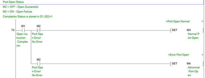
M2 – Good/Bad Port Open – ON indicates failure -
M3 – Good Port Open
M4 – Bad Port Open
The value of 0 is loaded into D0 to indicate using configuration from PLC Parameters
This bit of code opens the defined connection when M0 is turned on.

This section of code enables M3 if the Port opens with no error.
Next the data is sent
[ZP.BUFSND "U0" K1 D10 D20 M200]
where:
“U0” – Module to access
K1 – Channel to use to send data
D10 – Control Data for Socket Send Command – see manual for
system information -
D20 – The Start where Send Data is Stored
M200 - Bit to indicate Completion of Socket Send
Instruction
M201 - Good/Bad Socket Send– ON indicates failure –
D20 is set to the number of words that the BUFSND instruction will send and must match the setting of the BUFSND Event Trigger defined on the in node. The section titled Defining a trigger for a Mitsubishi unsolicited message provides details on how to define a Trigger that will execute upon receipt of a BUFSND message. In this example D20 is set to 8 and the data that will be sent is contained in D21-D28.
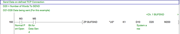
In the sample code shown above, setting the bit M0 will open the TCP Connection between the Mitsubishi CPU and the Mitsubishi Listener device. Setting bit M5 will send the BUFSND message to the Mitsubishi Listener.