The Workbench provides the view into a node's installation, configuration and resource definition. The Workbench also provides access and control over those resources.
A device is a resource that can represent a physical device, such as a programmable logic controller (PLC), an RF tag reader or a sensor. A device can also be defined in one node to represent a device that is defined and supported in another node. This allows your application solution to have access to devices and their data independent of their location or connectivity details.
To define a device that represents a Fanuc device, follow these steps:
If you have a Fanuc Robot, R553 (HMI Device (SNPX)) software must be installed on the controller
- From the Workbench left pane, expand the node where
you want to define the device.
- Select the Devices icon.
The Devices window appears as the right pane.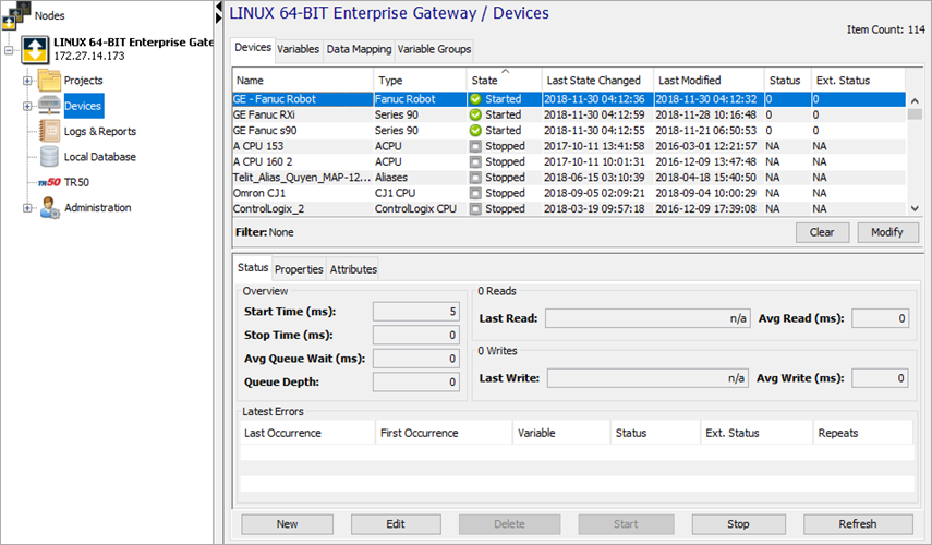
The Devices window provides a table format that lists the previously defined devices. - To define a new device, select New
at the bottom of the pane.
The Device window appears. The available device types are determined by the device support that is installed in the node. - Use the Type down-arrow, to select
Series 90 or Fanuc
Robot under the Fanuc group. When creating a device that
communicates with a RX3i CPU PLC, select the
Series 90 device type.
The Device window changes to accommodate the selected device type.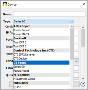
- To define a device that represents a Fanuc
device, set this new device’s parameters as
follows:
Parameter
Description
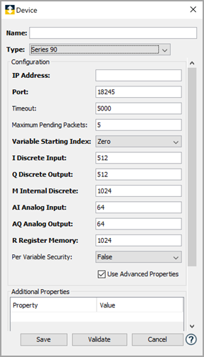
Name Enter a name for the Fanuc PLC device. Type Select Series 90 or Fanuc Robot. if you select Fanuc Robot, R553 (HMI Device (SNPX)) software must be installed on the controller
IP Address Enter the IP Address of the device. Port Enter the port number used by the device. The default is 18245. Timeout Enter the timeout value to use when communicating with this device. This is entered in milliseconds. The default value is 5000. You can also specify advanced settings for the device. Select the Use Advanced Properties checkbox.
Parameter
Description
Maximum Pending Packets The maximum number of sent packets that can be pending a response from the Fanuc device. Variable Starting Index Device Variables starting Index. If the value is zero, array index of variables starts at '0'. If the value is One, array index of variables starts at '1'. I Discrete Input Enter the size of discrete inputs defined in the device. Q Discrete Output Enter the size of discrete outputs defined in the device. M Internal Discrete Enter the size of of internal discretes defined in the device. AI Analog Input Enter the size of of analog inputs defined in the device. AQ Analog Output Enter the size of of analog outputs defined in the device. R Register Memory Enter the size of of register memory defined in the device. Per Variable Security Select False to disable the allocation of additional memory to track User to Variable access for all Variables in this Device. Select True to enable this feature if required. For more information, see Setting up Read Write per device variable - Click Validate to have the
parameters validated and to connect to the Fanuc
device. If there is a problem connecting to the Fanuc device, an error code will be displayed.
- Click Save to save the device
definition. The device will appear in the Devices
window list of devices.
- You can now control the device
(Start, Stop), access
the device’s variables by using the
Variables window, and build solutions
that use the device’s resources. For more information on sending appropriate commands to perform certain action on the Fanuc robots, see deviceWISE Fanuc driver Register Interfaces.