Step 2 - Defining a transport map for the WebSphere MQ transport
This section describes the steps to define a transport map for the WebSphere MQ transport you created in Step 1.
A transport map defines the parameters that come from a trigger (your application) and the mapping or formatting of those parameters to fields in the message that gets sent to the WebSphere MQ data queue.
For this example, you will specify the format of the message as ASCII. Once the message format is specified, you will create map variables that will comprise the message.
Assumption
It is assumed that you have completed Step 1 - Defining the WebSphere MQ transport.
Procedures
The transport map consists of a collection of input map variables that you define. The plant floor engineer will see these variables when defining the trigger. During runtime, the PLC device variables are set to the transport map variables.
Follow these steps:
- From the Workbench left pane, expand the node that
you want to define the transport map.
- Expand Enterprise, right-click the
Transport Maps icon to display its
pop-up menu, and then select
New.
The Transport Map window appears.
- In the Name parameter, enter
MyFirstTransportMap as the name for
the transport map.
- Use the the Transport Type
down-arrow, and then select WMQ.
Only WMQ transports that are available for the current node will be listed in the Transport Name drop-down list.
- From the Transport Name drop-down list, select
MyWMQTransport. This is the transport
you created in
Step 1 - Defining the WebSphere MQ transport.
- From Version Mismatch drop-down
list, accept the default Fail.
The Fail option will immediately fail any trigger event that has a version mismatch between the current transport map and the transport map that was used in the trigger.
Summary example device variables and map variables
The following table lists four PLC data values the
transaction will send to the WebSphere MQ queue. These data
values will be passed to the map variables you will
create.
|
Device |
Map variables |
Data Type |
Length |
Value |
|---|---|---|---|---|
|
D[0]-D[3] |
var1 |
STRING |
8 |
ABCDEFGH |
|
D[4] |
var2 |
INT2 |
N/A |
123 |
|
D[6] |
var3 |
INT4 |
N/a |
456789 |
|
D[8] |
var4 |
FLOAT4 |
N/A |
3.14159 |
Creating the map variables
- From the Input tab at the top of
the Transport Map window, select
Add.
The New Item window appears.
- In the Name parameter, enter
var1 as the name of the map
variable.
- Next to Type, select the
down-arrow, and then select the data type that you want
assigned to the name. For this example
STRING.
- In the Length parameter, accept
the default of 8. The value specifies the maximum
number of characters in the string.
- In the Count parameter, accept the
default of 1. The value specifies the dimension of the
map variable (for this example a scalar).
- Select Add.
A row appears on the Input tab with the information you added.
- Repeat the steps to add all required map variables:
- var2 as a INT2
- var3 as a INT4
- var4 as a FLOAT4
The final Input tab will look similar
to this:
You are now ready to specify the format of the payload and the map variables to use.
Specifying the payload
- On the Transport Map window, under the To
Enterprise section, select the
Format down-arrow, and then select
ASCII.
The Field Delimiter and Array Delimiter boxes become available. - The Field Delimiter box defaults
to a comma that is used to separate each ASCII string
element in a message. Accept the default comma. The
comma will be used to separate each ASCII element in a
message.
- The Array Delimiter box defaults
to an underscore ( _ ) character that is used to
separate an array of numbers. Accept the default
underscore.
When you select ASCII, there are also Field and Details columns. These columns will contain the map variables from the Input tab that you specified in Creating the map variables above. - Under the To Enterprise section,
select Add.
- Select the Field down arrow, and
then select var1 from the list.
- Repeat steps 3 and 4 for var2,
var3, and var4.
The completed To Enterprise section will look similar to this: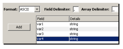
Notice that all four data types for the payload are strings. This is because the entire payload is defined as an ASCII string. The INT2, INT4, and FLOAT4 values will be converted to strings prior to insertion into the payload. - If you want to add a descriptive comment in the
payload, select Add one more time and
then select $CONSTANT in the
Field column.
Now that you have completed the transport map, you can test the input values. - Select Validate.
If the transport map was correctly defined, a window that contains the map output appears.
At runtime, the variables will be substituted with the values from the Local CPU formatted as ASCII. - Select OK to clear the validation
window.
- Select Save.
The new transport map is saved tot he node and will be listed on the Transport Maps tab.
The next step is to define a trigger that use the
transport map to send data to the WebSphere MQ data queue.
Go to
Step 3 - Defining a trigger to send data to a WebSphere MQ
queue.