Step 3 - Defining a trigger to send data to a WebSphere MQ queue
This section describes the steps to define a trigger that uses the WebSphere MQ transport to send a message to a WebSphere MQ data queue.
Assumptions
The following is assumed:
- Using the Workbench, you know how to create and start a project.
- You have completed Step 2 - Defining a transport map for the WebSphere MQ transport
Example project
This section describes the steps to define a project, which will be where the trigger is defined.
A project is a container item that is used to organize and control triggers.
Follow these steps to create a project.
- From the Workbench left pane, expand the node where
you want to define the project.
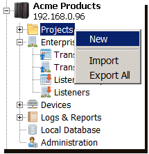
- Select the Projects icon,
right-click to display its pop-up menu, and then select
New.
The Create Project window appears.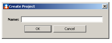
- Enter Acme Products as the name
for the project, and then select OK. A
project name can be up to 32 characters in length and
can include letters, numbers, and the underscore
character. Spaces are allowed.
The new project is added to the node and listed on the Projects tab. - From the Projects tab, select the
project, right click to display its pop-up menu, and
then select Start.
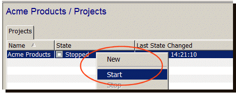
The project's State will change to Started.
You are now ready to create the trigger.
Example schedule trigger
To define a schedule trigger, follow these
steps:
- From the Workbench left pane, expand the node where
you want to define the trigger.
- Select the Projects icon, and then
from the right hand pane Projects tab,
double click our example project Acme
Products.
The Acme Products tab appears as the active tab for the right hand pane.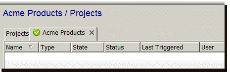
For this example, the tab is empty because no triggers have been defined in the project. Each project's tab will list the triggers that are defined in (or belong to) the project. - From the bottom of the project tab, select the
New button.
The Trigger window appears.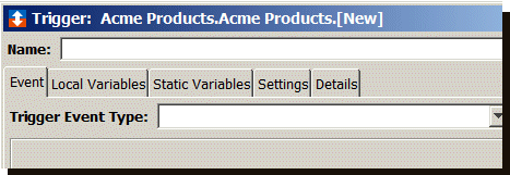
- In the Name parameter, enter
MyFirstTrigger as the name of the
trigger. A trigger name can be up to 64 characters and
include letters, numbers, and the underscore character.
Spaces are allowed.
- From the Event tab, select the Trigger
Event Type down-arrow, and then select
Schedule.
The Event tab becomes active with parameters that are appropriate for a schedule trigger.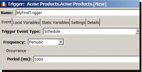
- From the Frequency drop-down list,
accept Periodic as the option you want
to use. The Periodic option means a
trigger will execute periodically at the specific
millisecond interval.
- Under Occurrence, in the
Period (ms) parameter, enter a value
of 5000. This will set the trigger to execute every
5000 milliseconds (every 5 seconds).
- Select the Settings tab.
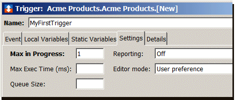
- In the Max in Progress parameter,
accept the default value of 1. A value of one indicates
that only one instance of the trigger can execute at a
time. The trigger must complete its processing before
another instance of the trigger is allowed to
execute.
- From the Reporting drop-down list
accept the default value of Off. A value of off
indicates that a trigger report, with the details of
the trigger and its actions at execution time, is not
generated or written to the Reports Log.
- In the Max Exec time (ms)
parameter, enter a value in milliseconds for the
maximum execution time for the trigger. If the trigger
exceeds this value, a warning message is logged in the
Exceptions
Log (even though Reporting parameter might be set
to Off). For this example, enter 4000 (4000
milliseconds or 4 seconds).
- The Editor mode drop-down list
provides the way you create and edit actions for the
trigger.
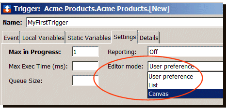
List lets you manually select an action from a list. For each possible output of an action, you select a route.
Canvas lets you drag and then drop an action on a drawing area. For each possible output of an action, you draw connectors between actions by dragging the mouse.
User preference remembers the option you used when editing the trigger.
For this example, List mode was selected and is used for the remaining steps. - Leave the Queue Size parameter
empty.
- The next step is to add an action to the trigger
that will send a message to the WebSphere MQ data
queue.
From the bottom of the Trigger window under the Actions pane, select Add.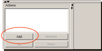
The New Action window appears.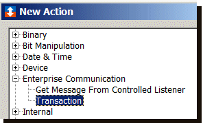
- Expand the Enterprise
Communication category, select
Transaction, and then select
Add. Other actions might be listed
under the Enterprise Communications
category.
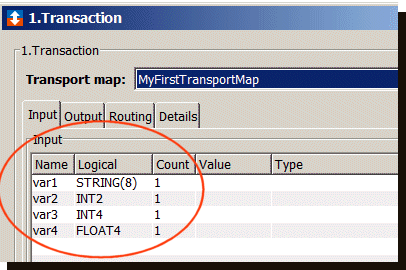
The bottom right pane of the Trigger window changes to accommodate the Transaction action. - Use the Transport map down arrow
to select MyFirstTransportMap.
- The Input tab becomes populated
with the names of the map variables from
MyFirstTransportMap.
Notice the names var1, var2, and so forth. These are the map variables you defined when the transport map was created. Also, notice the logical names defined in the transport map appear on the Input tab.
Associating variables with map variables
The next step in defining the trigger is to associate the actual device variables with the map variables listed in the transport map.
Follow these steps:
- From the Input tab, select the
right side of the Value column for the
var1 variable.
A list of device variables, macros, and other system variables appears.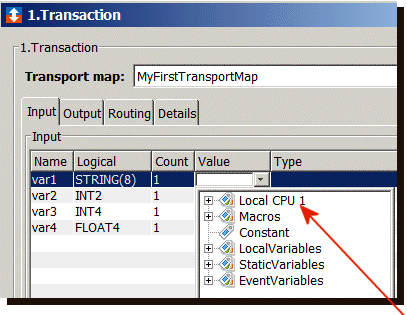
- For this example, you will map a device variable
(from the Local CPU 1 device) to the
var1 variable in the row.
- Expand Local CPU 1, and then
expand D to display a list of data
registers for that device.
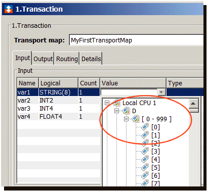
- Under D, expand
[0-999], and then select
[0] as the data register for the
var1 variable.
Note that STRING is the default value for this variable since its logical variable is also STRING. You can click the Type column and change the data type at any time.
Also note that the data will be treated as a STRING when it is read from the PLC and when it is delivered to the transaction. - Select the Value column for
variable var2.
- Under D, expand
[0-999], and then select
[4] as the data register for the
var2 variable.
Note that the data will be treated as a INT2 when it is read from the PLC and when it is delivered to the transaction. The transaction will convert the integer INT2 into a STRING when creating the payload. - Repeat steps 4 and 5 for var3, and
var4, applying the appropriate numeric
values.
When finished, the Input tab will be similar to the following: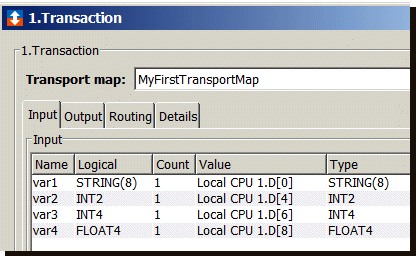
The trigger also has an Output tab that contains the resultStatus output variable.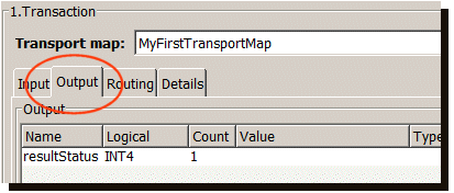
When the trigger executes, the resultStatus variable will contain a code indicating whether or not the transaction completed successfully. A zero indicates success. - Select the Routing tab. For the Failure route,
select ENDERR (end error).
- The trigger is completed, select
Validate.
- A message will tell you that the trigger definition
was validated. Select OK.
- Click Save.
The new trigger is saved to the node and listed on the Acme Products project tab.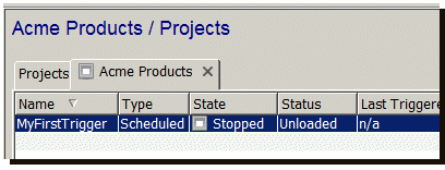
For the next step in this example, go to
Step 4 - Viewing the received WebSphere MQ
messages.