The Workbench provides the view into a node's installation, configuration and resource definition. The Workbench also provides access and control over those resources.
A device is a resource that can represent a physical device, such as a programmable logic controller (PLC), an RF tag reader or a sensor. A device can also be defined in one node to represent a device that is defined and supported in another node. This allows your application solution to have access to devices and their data independent of their location or connectivity details.
The following devices can be defined with the Mitsubishi driver:
- Q CPU
- Q CPU (Built-in Ethernet)
- L CPU (Built-in Ethernet)
- iQ-R CPU (Built-in Ethernet)
- FX3 CPU
- FX5 CPU
- GOT
- QnA CPU
- A CPU
Mitsubishi device types
The Mitsubishi device types available depend on the product your have installed along with the Mitsubishi drivers. The Mitsubishi device types and the details of their parameters may be different for your node type.
To define a device that represents a Mitsubishi PLC device, follow these steps:
- From the Workbench left pane, expand the node where
you want to define the device.
- Select the Devices icon.
The Devices window appears as the right pane.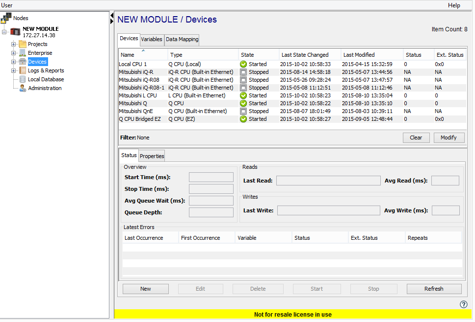
The Devices window provides a table format that lists the previously defined devices. - To define a new device,
select New at the bottom of the
pane.
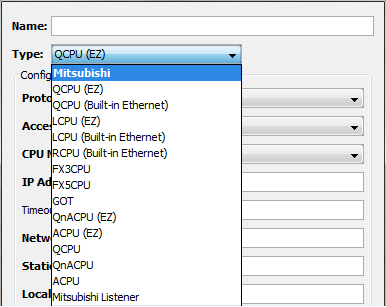
The Device window appears. The available device types are determined by the device support that is installed in the node. - Use the Type down-arrow to select
the specific device under
the Mitsubishi group for the CPU you
wish to connect to. This list will vary based on your
node type.
- The Device window changes to accommodate the
selected device type. The parameters displayed will be
modified based on the device type and possibly other
selections such as
Protocol and Use Advanced
Properties parameters:
-
Define the Mitsubishi device using parameters appropriate for the specific CPU type. The parameters for each CPU type are defined in the following sections.
- Select Validate to have the
parameters validated and to connect to the Mitsubishi
device. If there is a problem connecting to the
Mitsubishi device, an error code will be
displayed.
- Select Save to save the device
definition. The device will appear in the Devices
window list of devices.
- You can now control the device (Start, Stop), access the device’s variables by using the Variables window, and build solutions that use the device’s resources.
Defining a Mitsubishi Q Series CPU device
To define a device that represents a Q Series CPU device, repeat steps 3 through 8. Set this new device’s parameters as follows:
| Parameter | Description |
|---|---|
| Name | Enter a name for the Q Series CPU device. |
| Type | Select QCPU. |
| Protocol | Select TCP or BRIDGE |
| IP Address | Enter the IP Address of the device.
This field is displayed if the Protocol
field has a value of TCP. See Configuring a Q Series CPU for details on setting/obtaining the IP Address for a Q series CPU. |
| CPU
Number |
The position of the device in the rack. Numbering starts with 1 from the left (closest to the power supply). The default value is 1. |
| Port | Enter the port number used by the device. The default is 5002. |
| Network Number | The network number of the remote network module. This field is displayed if the Protocol field has a value of BRIDGE |
| Station Number | The station number of the remote network module. This field is displayed if the Protocol field has a value of BRIDGE. |
| Relay IP Address | The IP Address of the module that will relay messages to the destination module. This field is displayed if the Protocol field has a value of BRIDGE. |
| Local Station Number | The station number of the module making the connection request. This field is displayed if the Protocol field has a value of BRIDGE. |
| Timeout | Enter the timeout value to use when communicating with this device. This is entered in milliseconds. |
| Keep Alive | Enter the number of seconds to wait before sending a heart beat message. The default is 180 seconds. |
| Maximum Connections | A numeric value that indicates the maximum number of asynchronous connections that the driver will attempt to make with this Q CPU device. The default value is 1, the maximum value is 10. |
| Maximum Pending Packets |
The maximum number of packets sent that are pending a response from the PLC on each connection. This field is displayed if the Protocol field has a value of TCP.
|
| SD Points | Enter the number of SD points defined on the CPU. |
| SM Points | Enter the number of SM points defined on the CPU. |
| Enable Multi Block Read/Write | If user enables this property, multiple variables are added in a single read/write request to the Device, getting as a result a better performance in read/write. |
| Label Definition | Enter the location and the name of the
.csv file that contains the Label
definitions that were exported from the
QCPU. The  button can be used to locate the Labels
.csv file in the node's Staging Browser
area. Additional information about
this feature is provided at the bottom of
this page.
button can be used to locate the Labels
.csv file in the node's Staging Browser
area. Additional information about
this feature is provided at the bottom of
this page. |
| Per Variable Security | Select False to disable the allocation of additional memory to track User to Variable access for all Variables in this Device. Select True to enable this feature if required. For more information, see Setting up Read Write per device variable. |
| Remote Password |
Enter the Remote Password to unlock, if the PLC enabled password access. Password can be set by the GX Works 3. Displays encrypted password in the property text. |
| Enable Read Bit Access from Word |
If this property is enabled, Read Bit Access will be available as BOOL for Word Data type Variables. Variable Write is not supported and an Error is returned on attempting Write. |
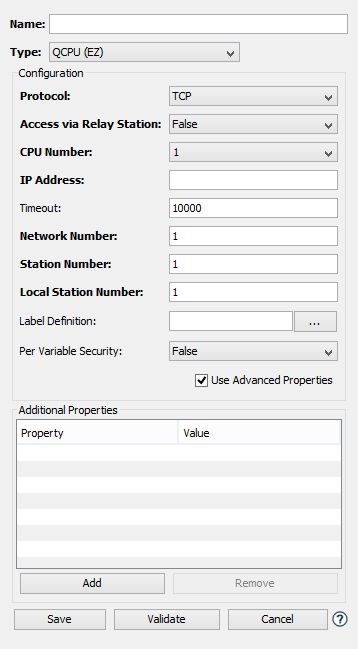
Defining a Mitsubishi Q CPU (EZ) device
To define a device that represents a Q Series CPU device using the Mitsubishi EZ Socket protocol, repeat steps 3 through 8. Set this new device's parameters as shown.
| Parameter | Description |
|---|---|
| Name | Enter a name for the Mitsubishi Q CPU (EZ) device. |
| Type | Select QCPU (EZ). |
| Protocol | TCP, UDP, or BRIDGE |
| Access via Relay Station | True, access to the CPU is made through a Relay Station, making a bridged connection to the destination CPU. False, connection is made directly to the CPU. This parameter is not available for BRIDGE Protocol selections. |
| CPU Number | The position of the device in the rack. Numbering starts with 1 from the left (closest to the power supply). The default value is 1. |
| IP Address | The IP Address of the device. This field is displayed if the Protocol is TCP or UDP and the Access via Relay Station value is False. |
| Timeout | Enter the timeout value to use when communicating with this device. This is entered in milliseconds. |
| Network
Number |
The network number of the remote network module. |
| Station Number | The station number of the remote network module. |
| Relay IP Address | The IP Address of the module that will relay messages to the destination module. This field is displayed if the Access via Relay Station value is True. |
| Relay Station Number | The station number of the module that will relay messages to the destination module. This field is displayed if the Access via Relay Station value is True. |
| Local Network Number | The network number of the node. |
| Local Station Number | The station number of the node. |
| Enable Multi Block Read/Write | If user enables this property, multiple variables are added in a single read/write request to the Device, getting as a result a better performance in read/write. |
| Label Definition | Enter the location and the name
of the .csv file that contains the Label
definitions that were exported from the
QCPU. The
button can be used to locate the
Labels .csv file in the node's Staging
Browser area. Additional information about
this feature is provided at the bottom of
this page. |
| Per Variable Security | Select False to disable the allocation of additional memory to track User to Variable access for all Variables in this Device. Select True to enable this feature if required. For more information, see Setting up Read Write per device variable. |
| Enable Read Bit Access from Word |
If this property is enabled, Read Bit Access will be available as BOOL for Word Data type Variables. Variable Write is not supported and an Error is returned on attempting Write. |
Defining a Mitsubishi Q Series CPU with Built-in Ethernet, an L Series CPU with Built-in Ethernet, or an iQ-R CPU with Built-in Ethernet
To define a device that represents a Q CPU with Built-in Ethernet or L Series CPU with Built-in Ethernet that is not in the same rack as the MESInterface IT CCPU, with communication over Ethernet, repeat steps 3 through 9. Set this new device’s parameters as follows:
| Parameter | Description |
|---|---|
| Name | Enter a name for the Q CPU with Built-in Ethernet device, L Series CPU with Built-in Ethernet device, or iQ-R CPU with Built-in Ethernet device |
| Type | Select QCPU (Built-in Ethernet), LCPU (Built-in Ethernet), or RCPU (Built-in Ethernet) |
| Protocol | Select TCP. |
| IP Address | Enter the IP Address of the
device. See Configuring a Q CPU with Built-in Ethernet or L Series CPU for details on setting/obtaining the IP Address for a Q CPU (Built-in Ethernet) or L Series CPU (Built-in Ethernet).See Configuring an iQ-R CPU with Built-in Ethernet for details on setting/obtaining the IP Address for a iQ-R CPU (Built-in Ethernet) |
| Port | Enter the port number used by the device. The default for the Q CPU (Built-in Ethernet), the L CPU (Built-in Ethernet), and the iQ-R CPU (Built-in Ethernet) is 5012. |
| Timeout | Enter the timeout value to use when communicating with this device. This is entered in milliseconds. |
| Keep Alive | Enter the number of seconds to wait before sending a heart beat message. The default is 180 seconds. |
| Maximum Connections | A numeric value that indicates the
maximum number of asynchronous
connections that the driver will
attempt to make with this Q CPU with
Built-in Ethernet or L Series CPU
(Built-in Ethernet). The default value
is 1, the maximum value is 10.
The iQ-R (Built-in Ethernet) does not allow multiple connections to one port. If multiple iQ-R (Built-in Ethernet) device connections are needed to one iQ-R CPU, then multiple ports will have to be defined on the iQ-R CPU. See Configuring an iQ-R CPU with Built-in Ethernet for details on defining ports on an IQ-R CPU. |
| SD Points | Enter the number of SD points defined on the CPU. |
| SM Points | Enter the number of SM points defined on the CPU. |
| Enable Multi Block Read/Write | If user enables this property, multiple variables are added in a single read/write request to the Device, getting as a result a better performance in read/write. |
| Label Definition | This feature is available for
QCPU (Built-in Ethernet) and
RCPU (Built-in
Ethernet) types. Enter
the location and the name of the .csv file
that contains the Label definitions that
were exported from the QCPU. The button can be used to locate the
Labels .csv file in the node's Staging
Browser area. Additional information about
this feature is provided at the bottom of
this page. |
| Per Variable Security | Select False to disable the allocation of additional memory to track User to Variable access for all Variables in this Device. Select True to enable this feature if required. For more information, see Setting up Read Write per device variable. |
| Remote Password |
Enter the Remote Password to unlock, if the PLC enabled password access. Password can be set by the GX Works 3. Displays encrypted password in the property text. |
| Enable Read Bit Access from Word |
If this property is enabled, Read Bit Access will be available as BOOL for Word Data type Variables. Variable Write is not supported and an Error is returned on attempting Write. |
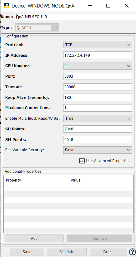
Defining a Mitsubishi QnA Series CPU device
To define a device that represents a QnA Series CPU device, repeat steps 3 through 9. Set this new device’s parameters as follows:
| Parameter | Description |
|---|---|
| Name | Enter a name for the QnA Series CPU device. |
| Type | Select QnACPU. |
| Protocol | Select TCP. |
| IP Address | Enter the IP Address of the
device. See Configuring a Q Series CPU for details on setting/obtaining the IP Address for a QnA series CPU. |
| CPU
Number |
The position of the device in the rack. Numbering starts with 1 from the left (closest to the power supply). The default value is 1. |
| Port | Enter the port number used by the device. The default is 5002. |
| Timeout | Enter the timeout value to use when communicating with this device. This is entered in milliseconds. |
| Keep Alive | Enter the number of seconds to wait before sending a heart beat message. The default is 180 seconds. |
| Maximum Connections | A numeric value that indicates the maximum number of asynchronous connections that the driver will attempt to make with this QnA CPU device. The default value is 1, the maximum value is 10. |
| SD Points | Enter the number of SD points defined on the CPU. |
| SM Points | Enter the number of SM points defined on the CPU. |
| Enable Multi Block Read/Write | If user enables this property, multiple variables are added in a single read/write request to the Device, getting as a result a better performance in read/write. |
| Per Variable Security | Select False to disable the allocation of additional memory to track User to Variable access for all Variables in this Device. Select True to enable this feature if required. For more information, see Setting up Read Write per device variable. |
| Enable Read Bit Access from Word |
If this property is enabled, Read Bit Access will be available as BOOL for Word Data type Variables. Variable Write is not supported and an Error is returned on attempting Write. |
Defining a Mitsubishi FX3 CPU device
To define a device that represents a FX3 series CPU device, repeat steps 3 through 9. Set this new device’s parameters as follows:
| Parameter | Description |
|---|---|
| Name | Enter a name for the Mitsubishi FX device. |
| Type | Select FX3CPU. |
| Protocol | Select TCP. |
| IP Address | Enter the IP Address of the
device. See Configuring a FX3U ENET connection for details on setting/obtaining the IP Address for Mitsubishi FX series PLCs that utilize the FX3U-ENET communication module. |
| Port | Enter the port number used by the device. The default value is 1025. |
| Timeout | Enter the timeout value to use when communicating with this device. This is entered in milliseconds. |
| Keep Alive | Enter the number of seconds to wait before sending a heart beat message. The default is 180 seconds. |
| D Points | Enter the number of D points defined on the CPU. |
| M Points | Enter the number of M points defined on the CPU. |
| R Points | Enter the number of R points defined on the CPU. |
| X Points | Enter the number of X points defined on the CPU. |
| Y Points | Enter the number of Y points defined on the CPU. |
| S Points | Enter the number of S points defined on the CPU. |
| Per Variable Security | Select False to disable the allocation of additional memory to track User to Variable access for all Variables in this Device. Select True to enable this feature if required. For more information, see Setting up Read Write per device variable. |
Defining a Mitsubishi FX5 CPU device
To define a device that represents a FX5 CPU device, repeat steps 3 through 9. Set this new device’s parameters as follows:
| Parameter | Description |
|---|---|
| Name | Enter a name for the Mitsubishi FX5U device. |
| Type | Select FX5CPU. |
| IP Address | Enter the IP Address of the device. |
| Port | Enter the port number used by the device. The default value is 1025. |
| Timeout | Enter the timeout value to use when communicating with this device. This is entered in milliseconds. |
| Keep Alive | Enter the number of seconds to wait before sending a heart beat message. The default is 180 seconds. |
| X Points | Enter the number of X points defined on the CPU. |
| Y Points | Enter the number of Y points defined on the CPU. |
| L Points | Enter the number of L points defined on the CPU. |
| F Points | Enter the number of F points defined on the CPU. |
| M Points | Enter the number of M points defined on the CPU. |
| B Points | Enter the number of B points defined on the CPU. |
| D Points | Enter the number of D points defined on the CPU. |
| W Points | Enter the number of W points defined on the CPU. |
| SW Points | Enter the number of SW points defined on the CPU. |
| SB Points | Enter the number of SB points defined on the CPU. |
| SM Points | Enter the number of SM points defined on the CPU. |
| SD Points | Enter the number of SD points defined on the CPU. |
| Per Variable Security | Select False to disable the allocation of additional memory to track User to Variable access for all Variables in this Device. Select True to enable this feature if required. For more information, see Setting up Read Write per device variable. |
Defining a Mitsubishi GOT device
To define a device that represents a GOT (Graphical Operator Terminal) device, repeat steps 3 through 9. Set this new device’s parameters as follows:
| Parameter | Description |
|---|---|
| Name | Enter a name for the GOT device. |
| Type | Select GOT. |
| Protocol | Select TCP or UDP, based on the protocol configured in the GOT device. |
| IP Address | Enter the IP Address of the
device. See Configuring a GOT device for information on configuring a GOT device. |
| Port | Enter the port number used by the device. The default is 5021. |
| Timeout | Enter the timeout value to use when communicating with this device. This is entered in milliseconds. |
| Keep Alive | Enter the number of seconds to wait before sending a heart beat message. The default is 180 seconds. |
| Per Variable Security | Select False to disable the allocation of additional memory to track User to Variable access for all Variables in this Device. Select True to enable this feature if required. For more information, see Setting up Read Write per device variable. |
Defining a Mitsubishi A Series CPU device
To define a device that represents an A Series CPU device, repeat steps 3 through 9. Set this new device’s parameters as follows:
| Parameter | Description |
|---|---|
| Name | Enter a name for the A Series CPU device. |
| Type | Select ACPU. |
| Protocol | Select TCP. |
| IP Address | Enter the IP Address of the
device. See Configuring an A Series CPU for details on setting/obtaining the IP Address for a Mitsubishi A Series CPU. |
| Port | Enter the port number used by the device. |
| Timeout | Enter the timeout value to use when communicating with this device. This is entered in milliseconds. |
| Keep Alive | Enter the number of seconds to wait before sending a heart beat message. The default is 180 seconds. |
| D Points | Enter the number of D points defined on the CPU. |
| X Points | Enter the number of X points defined on the CPU. |
| Y Points | Enter the number of Y points defined on the CPU. |
| M Points | Enter the number of M points defined on the CPU. |
| F Points | Enter the number of F points defined on the CPU. |
| W Points | Enter the number of W points defined on the CPU. |
| B Points | Enter the number of B points defined on the CPU. |
| R Points | Enter the number of R points defined on the CPU. |
| M9000 Points | Enter the number of M9000 points defined on the CPU. |
| D9000 Points | Enter the number of D9000 points defined on the CPU. |
| Per Variable Security | Select False to disable the allocation of additional memory to track User to Variable access for all Variables in this Device. Select True to enable this feature if required. For more information, see Setting up Read Write per device variable. |
Defining a Mitsubishi QnA CPU (EZ) or a Mitsubishi A CPU (EZ) device
To define a device that represents a QnA CPU (EZ) device or an A CPU (EZ) device, repeat steps 3 through 9. Set this new device’s parameters as follows:
| Parameter | Description |
|---|---|
| Name | Enter a name for the Mitsubishi QnA CPU (EZ) or A CPU (EZ) device. |
| Type | Select QnACPU (EZ) or ACPU (EZ). |
| Protocol | Select BRIDGE. |
| Timeout | Enter the timeout value to use when communicating with this device. This is entered in milliseconds. |
| Network Number | The network number of the remote network module. |
| Station Number | The station number of the remote network module. |
| Enable Multi Block Read/Write | If user enables this property, multiple variables are added in a single read/write request to the Device, getting as a result a better performance in read/write. |
| Per Variable Security | Select False to disable the allocation of additional memory to track User to Variable access for all Variables in this Device. Select True to enable this feature if required. For more information, see Setting up Read Write per device variable. |
Label Support
Using the GxWorks 2 software for the QCPUs and the GXWorks 3 software for the RCPUs, Labels can be created as a mnemonic to identify specific memory regions within the PLC. Using the GxWorks software, the Labels can be exported to a file that contains a .csv extension. An enhancement has been made to the Mitsubishi device drivers to use a Label definition file to enumerate additional variables for a Mitsubishi device. This enhancement is available for devices that connect to QCPU PLCs and RCPU PLCs. To use this feature the .csv file that was exported using GxWorks must reside in the Staging Browser area of the node. The .csv file will be parsed by the driver when the device is started. The Labels defined in the file will be represented as items in the Variables window for the Mitsubishi devices. Note that although the GxWorks software allows the creation of labels that can be up to 255 characters in length, the maximum length of a deviceWISE variable is 128 characters. Label items will be enumerated within a structure named Labels, which itself requires six characters plus one character for the period separator. This means the maximum length for a label is 121 characters. Labels that are greater than 121 characters in length will be truncated to the 121 character limit.
Enable Multi Block Read/Write
When using RCPU, RCPU (Built-in Ethernet), QCPU or QnACPU, it is possible to enable or disable the Multi Block Read/Write property.