For Rockwell driver troubleshooting, the following sections list common tasks and problems and a list of Rockwell driver error codes.
The features and functions available in a node are controlled by the licenses that are installed in the node.
To verify that the Rockwell driver license is installed:
- From the Workbench left pane, expand the node whose
license you want to check, and then select the
Administration icon.
- From the Administration window, select the
Licenses tab.
- Select the appropriate license. Details of the
license appear on the tab.
- View the Features field to identify the device driver.
If you do not see the correct license, or if the license is expired, you must request a license from your license key provider.
For information on how to install a license, refer to System Administration > Licenses.
If using the Data Table Write feature, check if the Cached option is selected. It is advised to deselect it, seeing that messages bigger than 480 bytes are prone of being fragmented. The cached option could lead to the continued resending of the last fragmented message by the PLC, which will confuse the Listener.
The number of active devices or connections exceed the total active device license count.The server or listener device will reject the connection attempt.
A system generated Alert will be displayed when the number of active device licenses in use exceeds a threshold percentage of the total active device licenses for the node. The Alert is cleared when the usage drops below the threshold percentage. For example, the system is currently using 90% of the available 200 device licenses.
An Exceptions Log message is inserted for the first connection rejection. For example, Device connection rejected due to insufficient device licenses.
For more information, see Licenses.
The device information on the Devices panel for a started server or listener device displays counts on its Attributes sub-tab:
- License In-Use
- License Rejected.
The Rockwell driver is not part of this node's installation. The Rockwell driver is installed as a package separate from the base product installation.
You may be working with different levels of nodes, each with different levels of support for devices. Ensure that this node is the one with support for Rockwell PLCs.
For information on how to add the Rockwell driver package, refer to System Administration > Packages.
If you are encountering sporadic timeout errors, the problem is either that you have configured the Max Pending Packets too high in the device definition, or the PLC is too busy servicing other requests, and the requests from the nodes are getting dropped by the PLC. The best recourse is to use the RSLogix 5/500/5000 communication diagnostics to debug the problems.
Check the battery status lights for a problem with the battery.
For ControlLogix and CompactLogix devices, check the enumerate tags parameters in the device definition.
If one or more devices with a large number of variables are started, the available memory in the node may be allocated to the point that the node cannot operate properly. Define and start devices one at a time and review the node’s memory usage on the Administration window, Node Administration tab.
If possible, reduce the amount of memory required for each device by using the Per Variable Security, Enumerate Controller Tags and Enumerate Program Tags configuration parameters in the device definition. For more information, see Using the Workbench to define Rockwell devices.
The network and PLC configuration may lead to extended Read or Write processing times, which cause frequent Read or Write timeout errors.
The Rockwell Driver accepts an Additional Properties value for the ControlLogix and CompactLogix device types that is used for the Read and Write timeout value when communicating with these devices. In the Device window, Additional Properties section, select Add to display the New Item popup. Enter “message_ttl” (without the quotes) for the Property field and a timeout value in the Value field between 1 and 31. The units are seconds. If a value outside of this range is used, the default of 10 is used. For more information, see Using the Workbench to define Rockwell devices.
At times it may appear that the Rockwell driver is not processing the unsolicited messages that the Rockwell PLC is sending. Remember that there is a one-to-one relationship between an unsolicited message defined on a Rockwell PLC and a trigger. If you find the unsolicited messages being sent are not being processed by your trigger, check the following areas to locate the problem.
- Verify that you have defined an Unsolicited Logix
Listener device on your node. Ensure that the
Unsolicited Logix Listener device is in a Started
state.
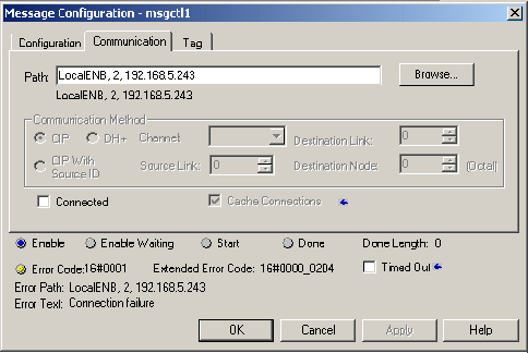
- Verify that the Path value on the Communication tab
of the RSLogix Message Configuration panel is
referencing the IP address of the node.
- For the Set Single
Attribute and Custom command
types, ensure that the Service Code, Class, Instance,
and Attribute values entered on the Message
Configuration panel of the RSLogix software matches the
Service Code, Class, Instance, and Attribute values
entered in the Workbench Trigger Definition panel of
the trigger associated with the Unsolicited Logix
Message event trigger. These fields must match
exactly.
- Verify that the Service Type value selected on the
Message Configuration panel of the RSLogix software
matches the Command value selected on the Workbench
trigger definition panel. RSLogix Set Attribute Single
selection corresponds with the Set Single Attribute
trigger event type, while the RSLogix Get Attribute
Single selection matches the Get Single Attribute
trigger event type.
- Verify that the Source Length value specified in
the RSLogix Message Configuration panel matches the
Input Length value specified in the trigger definition
panel. This applies to the Set Single
Attribute or Custom command
types.
- For the Data Table Write command,
verify that the value in the Size of One Element
(bytes) field, which is displayed for String and Binary
data types, matches the length of the String or the
User Defined Type, being sent in the message. The
message does not contain String or UDT lengths, so this
information is required to correctly parse the message
data for these two data types.
- Verify that the unsolicited message is indeed being sent by the Rockwell PLC. This is done using the Workbench tool to browse the Variables associated with the Unsolicited Logix Listener. This panel will show what PLCs are connected to the Unsolicited Logix Listener and what messages have been received by the Unsolicited Logix Listener. See the Using the Variables window to access Rockwell device variables section for more information.
The default port used by the Rockwell driver's Unsolicited Logix Listener device is 44818. This is the default CIP port and is used by other CIP enabled products, such as the Rockwell RSLinx software and also the Omron driver's CIP Listener.
If the RSLinx software is on the same Windows machine as the Enterprise Gateway for Windows node - and the RSLinx software is started - this port conflict will prevent the Rockwell Unsolicited Logix Listener device from starting. In turn, this will prevent the listener from receiving unsolicited messages from the Rockwell Logix devices.
To remove the port conflict with the Rockwell RSLinx software
- Do not have the Rockwell RSLinx software installed
on the same machine as the Unsolicited Logix
Listener.
- If the Rockwell RSLinx software is installed on
the same machine, ensure that it is not running.
- If the Rockwell RSLinx software must be installed
and running on the same machine as the Unsolicited
Logix Listener, modify the port defined for the
Unsolicited Logix Listener. This will also require a
change to the ladder logic on the Rockwell ControlLogix
PLC. To do this, use the following step by step:
- From the Workbench, edit the device that is failing. Alter the Port field to one of your choice that is not in use, for example 44819, like the example bellow:
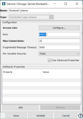
- At the Communicatin tab of the Rockwell Message Configuration window, edit the Path field. By default the message is
routed to port 44818. To have it rerouted it is necessary to specify the port, appending the colon character followed by the specific port number. For example, in the case provided, using the 44819 port, the Path would be: LocalENB, 2,
192.168.5.243:44819
- From the Workbench, edit the device that is failing. Alter the Port field to one of your choice that is not in use, for example 44819, like the example bellow:
If the Omron CIP Listener is started and using the same port as the Unsolicited Logix Listener, the Unsolicited Logix Listener will not be able to start. In this scenario messages sent by Rockwell ControlLogix PLCs would be processed by the Omron CIP Listener, since the format of the CIP protocol message is implemented in the same fashion by both PLC Vendors.
If you would like to use the Rockwell Unsolicited Logix Listener and the Omron CIP Listener on the same machine.
- Ensure that the two listeners are using separate
ports.
- Modify the Message command in the ladder logic on both the Rockwell ControlLogix PLC and the Omron NJ PLC to send their messages using the appropriate port.
As with the ControlLogix unsolicited messages, there is a one-to-one relationship between an unsolicited message defined on a Rockwell PLC-5 or SLC 500 and a trigger. If you find the unsolicited messages being sent are not being processed by your trigger, check the following areas to locate the problem.
- Verify that you have defined an Unsolicited
PLC-5/SLC 500 Listener device on your node. Ensure that
the Unsolicited PLC-5/SLC 500 Listener device is in a
Started state.
- Verify that the Ethernet (IP) Address value on the
MSG window of the RSLogix software is referencing the
IP address of the node.
- Ensure that the Data Table Address value entered on
the MSG Configuration panel of the RSLogix software
matches the Data Table Address value entered in the
Workbench trigger definition panel of the trigger
associated with the unsolicited message. These fields
must match exactly. Note that although Symbolic names
must be enclosed within quotation marks on the RSLogix
software, quotation marks are not to be entered in the
Data Table Address parameter in the Workbench. Using Logical names (Ex: N300:0) will not require the quotation marks on the RSLogix software.
- Verify that the Communication Command value
selected on the MSG Configuration panel of the RSLogix
software matches the Command value selected on the
Workbench trigger definition panel.
- Verify that the Size in Elements value specified in
the RSLogix MSG Configuration panel matches the Message
Length value specified in the trigger definition panel.
This can be tricky in that the value entered in the
RSLogix software is a number of elements, while the
value entered in the Workbench is a number of bytes.
Dividing the Message Length value in the Workbench by
the data size of the Workbench Message Type parameter
must equal the Size in Elements value specified in the
RSLogix software. As an example, a value of 256 maybe
entered as the Size in Elements value using the RSLogix
software. If the elements being sent are two byte
integers, then a value of 512 must be supplied in the
Workbench Message Length parameter. The Message Type
parameter must be set to INT2.
- Verify that the unsolicited message is indeed being
sent by the Rockwell PLC.
- Turn on the error reporting option in the trigger definition to see if the trigger is executed and the raw format of the associated data is present.
Rockwell PLC’s represent string data typed tags as a two
element structure. The first element, named LEN, is four
bytes and contains the actual length of the string.
Following these four bytes is the actual value of the
string. The following image shows how a tag named STRa1,
with a value of “helloworld”, is represented on a
ControlLogix device.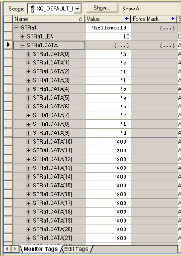
The LEN portion of the STRa1 tag consist of four bytes that
indicate the length of the string value in the STRa1 tag,
which is 10. The DATA portion of the STRa1 tag contains the
string value “helloworld”.
The Rockwell driver unsolicited message support for
payloads that contain String data typed tags assumes that
the message will contain both the LEN and the DATA portion
of the tag. The Rockwell driver assumes that the first four
bytes of the unsolicited message payload with String data
typed tags will contain the length of the string, followed
by the actual String data.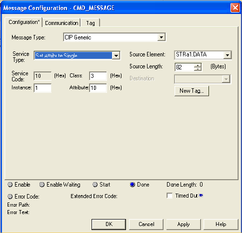
The Set Attribute Single tag definition above will result
in the first four bytes of the STRa1 tag’s value being
dropped by the trigger that processes it. In this situation
the Logix unsolicited message has been defined to send only
the DATA portion of the tag, bypassing the LEN element in
the tag. The Rockwell driver is expecting the first four
bytes to contain the LEN element and will copy the data
from the message beginning with the fifth byte in the
unsolicited message. In the previous image the STRa1 tag
contains the value of “helloworld”. A trigger receiving the
unsolicited message payload with a Source Element value of
STRa1.DATA will receive a payload of “oworld”.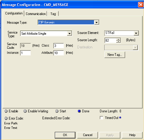
The correct way to define the unsolicited message to ensure
that the Rockwell driver receives the entire string
structure is to refer to the tag and not its elements. In
the example above the tag named STRa1 is referenced in the
Source Element field, ensuring that the Rockwell driver
will receive both the LEN element and the DATA element of
the tag. A trigger associated with the unsolicited message
shown above will now receive the entire string value,
“helloworld” in our example, in its payload.
Finally the trigger definition must account for the four
byte LEN element in string data typed payloads. The STRa1
tag is defined as an 82 byte string. The definition of a
trigger that receives this data must include the four byte
LEN field in its definition of the message payload.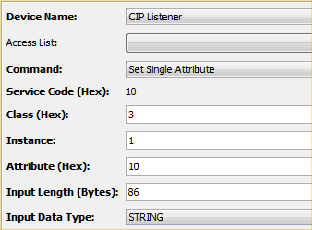
The Input Length (Bytes) field has been appropriately
defined to represent the full byte length of the STRa1
string tag, 86 bytes. The maximum string length of this tag
is 82 bytes, plus the 4 bytes needed to represent the
actual length of the string value in the field.
When the PLC software (Connected Components Workbench) is connected to the Micro820 or Micro850 PLC, the device will not be able to get to the Started state. Any device that is already in the Started state when the CCW connects continues to work for reads and writes.
Complete any PLC programming that might be in progress with the CCW, then disconnect the CCW. The device will now be able to get to the Started state.
Write-only variables can only be written as their basic type (INT1, INT2, INT4, etc). Bitwise writes are not supported, because the PLC must perform an implicit read of the variable before masking off and writing the desired bits.
The Micro800 reads and writes these types as unsigned 32-bit data, but it does not support bitwise access.
The valid ranges are shown below. Any value greater than these limits will result in error -6237 "Device protocol error" with extended status 3.
| Type | Range | Micro800 Values |
|---|---|---|
| DATE | 0 to 2147385600 | 1970-01-01 to 2038-01-14 |
| TIME | 0 to 4294967294 | 0s to 49d17h2m47s294ms |
This section describes the error codes that you might encounter when using the Rockwell driver. The Rockwell PLCs represent these error codes in a hexadecimal format and that format will be maintained by the driver. This format is used when the error codes are displayed in the Extended Status column in the Devices window. The Status column in the Devices window will always be a generic error code that can tell you if the error is a communication error, a data error, or some other internal device error. The value shown in the Status column will always be in a decimal format. The Extended Status column provides the error code from the driver. These error codes can be basic runtime error codes or specific to the Rockwell driver. The hexadecimal display of these codes may lead to some confusing error codes. The basic runtime error codes are negative numbers and will start with the characters 0xFFFF. An example of this would be the display of a value of 0xFFFFE3CA in the Extended Status column, which translates to a decimal value of -7222.
The error codes are also referenced in the Exceptions Log. When the system experiences an abnormal condition an error message, along with an error code and an extended error code are recorded in the Exceptions Log. Examples of abnormal conditions would be a device failure, a disconnect from a controller, or a software error. For more information, see Exceptions Log.
For ControlLogix and CompactLogix PLCs, the following error codes are returned as extended status codes from the Rockwell driver.
| Extended Status code | Error name | Action |
|---|---|---|
| 0x04 | This general status code means that the IOI could not be deciphered. Either it was not formed correctly or the match tag does not exist. | Protocol error; ensure that the driver supports the tag being accessed. |
| 0x05 | The particular item referenced (usually instance) could not be found. | The tag could not be found. This could indicate that the tag is not supported by the driver, or that the program has changed since the driver queried the tag information. Restarting the device may fix this issue. |
| 0x06 | The amount of data requested would not fit into the response buffer. Partial data transfer has occurred. | Too much data is being requested in a single request. Try breaking up the request into smaller reads/writes. |
| 0x0A | An error has occurred trying to process one of the attributes. | Protocol error; ensure that the driver supports the tag being accessed. |
| 0x13 | Not enough command data parameters were supplied in the command to execute the service requested. | Protocol error; ensure that the driver supports the tag being accessed. |
| 0x1C | An insufficient number of attributes were provided compared to the attribute count | Protocol error; ensure that the driver supports the tag being accessed. |
| 0x26 | The IOI word length is invalid | Protocol error; ensure that the driver supports the tag being accessed. |
Error code information taken from the Rockwell document Logix5000 Data Access, document no. 1756-RM005A-EN-E.
The following error codes are returned as extended status codes from the Rockwell driver for the SLC 500 and PLC-5 PLCs.
| Extended Status code | Error name |
|---|---|
| 0x01 | The node identified by the DST designation is out of buffer space. |
| 0x02 | The remote node specified is not responding |
| 0x03 | Duplicate token holder detected |
| 0x04 | Local port is disconnected |
| 0x05 | Application timed out waiting for a response |
| 0x06 | Duplicate node has been detected |
| 0x07 | The station is offline |
| 0x08 | Hardware fault |
| 0x10 | An illegal command was provided or the command format was not correct |
| 0x20 | The host has a problem and is not communicating |
| 0x30 | The remote node host is missing, is disconnected, or has been shut down |
| 0x40 | The host could not complete the function due to a hardware fault |
| 0x50 | Addressing problem or the item reference is in a memory protect rung |
| 0x60 | Function not allowed due to command protection selection |
| 0x70 | The Processor is in Program mode |
| 0x80 | Compatibility mode file is missing or communication zone problem |
| 0x90 | Remote node cannot buffer the command |
| 0xA0 | Wait ACK (1775-KA buffer full) |
| 0xB0 | Remote node problem due to download |
| 0xC0 | Wait ACK (1775-KA buffer full) |
The following are Rockwell extended status codes, the values of which are preceded by a value of 0xF0
| Extended Status code | Error name |
|---|---|
| 0XF001 | A field has an illegal value. |
| 0xF002 | Less levels specified in address than minimum for any address |
| 0xF003 | More levels specified in address than system supports |
| 0xF004 | Symbol not found |
| 0xF005 | Symbol is of improper format |
| 0xF006 | Address doesn't point to something usable |
| 0xF007 | File is wrong size |
| 0xF008 | Cannot complete request, situation has changed since the start of the command |
| 0xF009 | Data or file is too large |
| 0xF00A | Transaction size plus word address is too large |
| 0xF00B | Access denied, improper privilege |
| 0xF00C | Condition cannot be generated _ resource is not available |
| 0xF00D | Condition already exists _ resource is already available |
| 0xF00E | Command cannot be executed |
| 0xF00F | Histogram overflow |
| 0xF010 | No access |
| 0xF011 | Illegal data type |
| 0xF012 | Invalid parameter or invalid data |
| 0xF013 | Address reference exists to deleted area |
| 0xF014 | Command execution failure for unknown reason; possible PLC_3 histogram overflow |
| 0xF015 | Data conversion error |
| 0xF016 | Scanner not able to communicate with the 1771 rack adapter |
| 0xF017 | Type mismatch |
| 0xF018 | 1771 module response was not valid |
| 0xF019 | Duplicated label |
| 0xF01A | File is open; another node owns it |
| 0xF01B | Another node is the program owner |
| 0xF01E | Data table element protection violation |
| 0xF022 | Remote rack fault |
| 0XF023 | Timeout |
| 0XF024 | Unknown error |
Error code information taken from the Rockwell document DF1 Protocol and Command Set, document no. 1770-RM516_-EN-P.